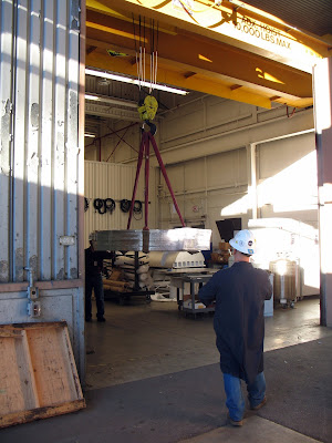
After many months of difficult work and re-work the MICE coupling coil finally shipped. It was good to see it go out finally ready for testing. I wrote a couple of articles about the work we were doing to the coil in anticipation to shipping to another facility for cryogenic testing.
At the end of the last article I mentioned we were nearing the final stages of completing the mechanical and instrumentation tasks needed for testing. One of the last operations needed to certify the coupling coil for testing was to leak check the cryogenic cooling tubes that wrap around the circumference of the coil.
The cooling tubes are heavy wall aluminum 6060 alloy. For this particular application this was the only available alloy in the correct metric size. In fact I had to look up this alloy so I could figure out what the differences are from the more common 6000 series aluminum alloys. There were some tricky forming operations required for these cooling tubes. A custom bending die was fabricated to form a tight bend in the tube near where it entered the reservoir box at the top of the coil.
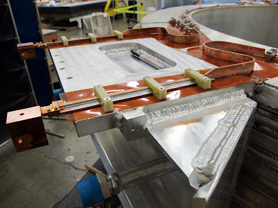
This is the heavy aluminum helium reservoir box. The cooling tubes make a tight bend to come from the circumference of the coil and emerge in the box where they connect to the helium system. This is where our big problem turned out to be.
During leak checking we discovered a very faint leak near the bend in the cooling tube. The leak was in the area close to where the tube entered the box. This made any attempt at repair difficult at best. The first repair attempt was to try to weld a patch over the suspected area to try to seal the leak.
I couldn't release it for shipping without one of the project managers signing off on it even though the leak we detected was extremely small. To put the size of the leak in perspective its something like one milliliter of gas through the leak per hundred years at standard pressure. The main concern was how the leak would behave when the coil was cooled off to superconducting temperatures, in the case of this magnet that's 1.9 Kelvin. Weird things happen at two degrees above absolute zero. Nobody wants to take any chances.
A couple of shots of the cooling tubes. They are fully welded around the circumference of the magnet coil. This improves conductivity between the tubes and the coil. To avoid softening the tubing excessively the welding interpass temperature was specified to be less than 150F. Even with all the special precautions we still ended up with a leak. But this is why we check these things. Trust but verify.
Here we are running nitrogen through the cooling tubes to dry any moisture out before we leak check. This is done to get the base pressure of the tube low enough to detect the tiniest leaks. On the right side of the picture is a gas heater that warms the gas coming off the nitrogen dewar before it circulates through the magnet cooling tube.
In this picture we are set up to leak check the tube. The vapor is liquid nitrogen from a cold trap that is protecting the leak detector from back streaming any junk from the tube. Unfortunately the patch didn't work and we had to come up with another plan to repair the cooling tube.
This magnet is part of a large international collaboration project. We did much of the assembly and instrumentation but lacked a cryogenic facility large enough to cool and test the magnet. This magnet will be tested in a gigantic cryostat at Fermilab in Illinois as part of this collaboration. During the repair there were many back and forth discussions on how to repair the leak, and follow all the necessary safety requirements of multiple institutions. The document trail on this project could reach all the way to Illinois if you laid the pages end to end.
After much discussion and planning the solution was to perform the equivilant of a heart bypass on the cooling tube. You can see in this picture how far we went trying to chase the leak in the tube. A lot of the removed material was just to provide access for the welding team to get to the area's that needed welding.
Finally the bypass was complete. The collaboration had decided that the tube needed a pressure test as well as a vacuum leak check. More discussions and back and forth with safety requirements. Eventually we performed a pressure test by filling the tube with water and pressurizing it to the required stress level for the test. One thing we don't mess around with is any safety requirements on jobs like this.
This is a good shot of the amount of welding needed to put this magnet together. Check out the gigantic MIG weld at the top of the casing. There is something like 85 Kilometers of superconducting wire wound around this glorified sewing bobbin.
At last we get to the final stages of the job. This is the final pressure test of all the cooling tubes on the magnet. The engineer in charge is smiling because it going according to plan and nothing is happening, just the way he wants. The more sensitive test is the final vacuum leak check after the pressure test. Just in case we stressed the tubes and inadvertently caused a new leak.
The pressure test setup from the reservoir box side. We installed a pressure relief valve to protect the tube from any possible overpressure situation. We filled the tubes with water and pumped the tube up to the test pressure in increments, holding at each pressure for ten minutes. You would swear the clock slows down when you have to time an interval like this multiple times. See the document on the table. That represents over two man months of work for the project mechanical engineer. This is a time when I'm really glad to not be a an engineer.
Not much danger of overpressure with this hand pump. The test pressure was close to the maximum this had pump could put out. You would have had to jump up and down on the lever to get the pressure to spike with this setup. All the tubes held pressure with no leakdown over the ten minutes.
So the coil finally passed all the pressure and vacuum requirements. We were released to package the coil for shipment to Fermilab. The project engineer was pretty happy about this. He got a wonderful weather day to finish the job.
The finished magnet weighs around 4000 lbs. Easy work for the assembly shop crane. Now is not the time to bump into anything. Ahmet gladly turned the crane controls over to me for this part.
Almost there. Behind me is one nervous engineer. He was visibly relieved when the magnet touched down in the crate.
We installed a bunch of these shock watch sensors on the crate and directly on the coil to monitor the shipment. On more fragile items we install an active accelerometers to the item that log the entire journey end to end. If there is a problem we can see when it occurred and the magnitude.
This is the end of the story for me. Its in the box and belongs to somebody else now. It was a challenging and interesting problem. Hey, if everything went perfect it would have been boring.
Five days later its back out of the box at Fermilab. The shockwatches on the crate were all tripped but the ones on the magnet were fine. The crate had it own special suspension system to cushion the ride across the country. Worth the extra cost for the crate.
Thanks for looking.


No comments:
Post a Comment