Monday, December 31, 2012

Diacro Heavy Ring Forming

Over the holidays I needed to form several rings from fairly large diameter steel rod. When I say large its kind of related to the forming method. For these they will be formed by hand cold. So 5/8 diameter is pretty close to my limit. The project is several spoked handwheels for a custom door installation in the art studio. There are several rod benders in the shop tool crib but for this job I pulled out the big  #2 Diacro bender. Its big and heavy and runs on roller bearings making it smooth and accurate for heavy duty bending. When I got this bender it didn't really have many of the factory accessories. Over the years I have cobbled together enough stuff to do most of the things I need but not in this case. For these handwheels a large center die was required to size the handwheels. Scrounging around the shop I came up with an old steel wheel that I made for testing on the English wheel. It was more than obsolete so it became the inner forming die for the handwheel rings. Guessing at the amount of springback it seemed close to what I was shooting for on the finished rings.
This is one of the proof rings. Its a little over six inches in diameter. The rod is 5/8 diameter copper plated steel. I wanted plain old cold rolled but all the steel suppliers I use in the Bay area for quick stuff were closed for New Years eve. I tried Lowes but almost died from sticker shock at the hobby metal rack. Lurking around the store I found this copper plated ground rod from the electrical department. The price was right and If I need to remove the copper plating it shouldn't be too hard.
Here is the re-purposed English wheel and a ring rod blank. The diameter of the die is large enough so that I can't use the standard eccentric pin to lock the blank in. I just tack welded it to the steel die to keep it from slipping. The first couple of tries the weld broke much easier than I thought it should. Upon further inspection it appears the copper plating is much thicker than I anticipated. This will most likely make these unsatisfactory for the handwheels but its still a fun forming project. The slope that's ground in the end of the rod is there for a purpose.
This is one of those jobs where using stainless filler to join two steel parts is beneficial. The standard steel rod E70S is less ductile than the stainless steel even though it has a higher tensile strength. The rod is actually bending right next to the weld so maximum ductility is more important than raw tensile strength. The copper needed to be fully removed to produce a weld strong enough to resist the forming forces.This is when I discovered just how thick the copper plating is on a ground rod.
Here is the ring blank ready to form. You need room all the way around the bender to form a full circle. Clear the area before you start bending because you don't want to release tension on the bender handle halfway through the bend. If you release tension you will be rewarded with inconsistent results and out of round rings.

Many years ago I wound a several long lengths of stainless tubing for a heat exchanger I was building. Think hillbilly type moonshine stills and you will be close. The tubes were so long I had to move one of the heavy welding tables out into the shop parking lot so I could get a full sweep with the long tube. I wish I had some pictures of that one. The tubing was 5/8 or 3/4 diameter and the coil was roughly twenty or twenty four inches in diameter. Several of the wound "springs" were connected to make the necessary length for the heat exchanger. The forming die was built up out of regular plywood and bolted to the welding table.
Some initial pre-bending on the start end. I'm putting almost yield pressure on the left hand holding the rod blank and then using minimal pressure on the bender handle to get the first part of the bend to lay up against the die better. This stresses the hold back device less which in this case is a weld.
Here we go. Make sure you have everything you need within arms reach when you start. Cheater is two inch pipe which was the only thing I had around that would fit around the Diacro handle.
Coming around nicely. You cant see it in this picture but I had to hop the cheater over the bench vise as I swept around. Once you get ninety degrees wrap on the pressure on the hold back weld is minimal.
Now you can see what the little ramp is for. To make rings you need to wind more than a full circle if you want the best looking and roundest rings. The ramp allows me to go up a turn on the die and continue around. I need to form well past the starting point still.
This 5/8 rod is stiff enough that I had to use a cheater to get the rod up to the next level. It was lifted up the ramp as It was being formed around the die.
Another shot of the same part of the process. All this time its important to keep pressure on the main handle so you don't lose any of the winding tension you have formed in.
I could probably stop here but its way better to have more overlap than you need than to come up any short of a full circle plus fudge factor.
Here is a shot after releasing the winding tension. The amount of spring back varies for a couple of reasons. The main reason is material condition. Harder materials spring more than soft ones. The second is the severity of the forming. This would qualify as semi severe. If this same rod was wound around a fifty five gallon drum the spring back as a percentage of the diameter would be much less. Material springback unfortunately is not a linear curve. It is the art part of bending. You get pretty good at predicting how much a particular setup will spring but for accurate results test bends are required. Start slightly large as its easier to make the die smaller that make it over larger. In sheet metal we call this springback material condition effect the K factor. It applies here with rod bending as well. Here is a link to a nice document on the Art of Bending. This was put out by the Diacro bender company about a thousand years ago. In the old days you got one with your bender and thats it. Now you can get it and download it online. Print it and put it in your shop book of knowledge.
The last step is to mark the rings and cut them. Pick a spot that has the correct radius in both ends of the ring. I like to cut them apart with a thin blade hacksaw or bandsaw.
Don't go too far and cut your die!
Viola! Two more to go. Shifting the rings sideways to mate them up is pretty easy compared to the main forming. They don't need much weld prep. I like to leave them slightly open, like the band saw kerf and just fill the gap as the weld prep. Be sure to build up the weld higher than the OD of the rod. It looks bad when somebody digs down below the natural surface of the rod to get the weld to clean up. Properly finished the weld will be almost invisible. I won't be welding these up because of the copper plating. I'll wait until I get some proper cold rolled steel for the job.

Thursday, December 27, 2012

Lathe Ergonomic Improvements

Over the last couple of days I have been working on shop infrastructure projects. A friend texted me the other day and asked how my Christmas went. I replied, "Great. UN-disturbed in the shop just the way I like it" I was able to do a couple of little jobs that were on my list to get the shop in smooth running shape.

I find that a shop will not run at its peak efficiency until these jobs kinds of jobs get done. I have seen shops that never do anything to improve the workflow, ergonomics and workspace needs of the folks working there. In the old days when the shop got slow the boss would have you do some of these jobs to make things run smoother when the real work came rolling back in. Over a period of years of this cycle you end up with a really nice shop setup.

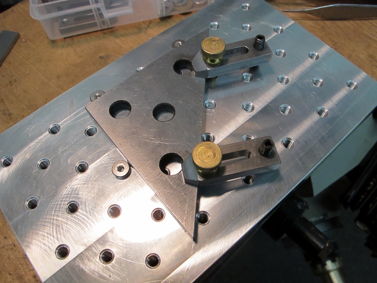
Many work place improvement items may seem trivial and unimportant at first glance but each contributes a small part in making your work more efficient and comfortable. As an example I did a time study many years ago just for fun. It involved two very innocent modifications to a drill chuck used in the vertical mill. The modifications were to remove the R-8 shank and replace it with a 5/8 straight shank that was further shortened to around an inch like the two in the picture below.
 Seems like a bunch of work for nothing right? Wrong. Think about how many times you move the knee of the mill up and down. The difference in length between the R-8 shank and the shortened 5/8 shank is about three inches. At .100 per rev on the knee handle that's thirty turns. So many times during the day you remove the chuck and replace it with an end mill. Drop the knee a few inches so you can actually remove the chuck, maybe change collets, insert end mill, raise the knee to get back into the work envelope. If you do this all day long its not hard to see that not cranking the knee twenty or thirty revs per tool change is going to add up quickly. The other thing I did was to get several sizes of commonly used end mills with 5/8 shanks on them. This saves a collet change on a few dozen of those tool changes. The point is this all adds up at the end of the week or year to potentially a significant time savings. Before power draw bars on manual mills became cheap and popular this was enough to bury the guy next to you with the Empire state building R-8 shank. Add a cheapskate knee feed and competition becomes glacial.

The first project I tackled over the holidays was a simple chip back splash for the new lathe. The lathe didn't come with one and looking over the manual and parts list I don't think they ever made one for this particular machine. The requirements are simple enough. The chips coming off the machine that go backward away from the operator want to be channeled into the chip pan at the bottom of the machine and kept off the floor if possible. My first choice would be to fabricate it from stainless sheet metal and mount it directly to the machine. This is a tough project when you don't have a shear and brake yet. I decided to make it from plywood and either paint or varnish it so it can be wiped clean. Note this is quite a few steps down from the stainless steel back splash I would build it if money and time were not a factor. Its more important to have something than to have the uncompleted fantasy guard.

The more I though about it the more I decided I really wanted a metal surface for the chips and oil to land on. I made up my mind to use plywood for the main structure and then bend up a thin sheetmetal skin for the resistance to oil and chips. Thin galvanized sheetmetal is fairly cheap and needs no paint and is easy to bend without a brake. The first step was to make the plywood structure.
Where my lathe is positioned it is near a sprinkler riser. The riser has a nice two inch pipe railing around it to protect the riser from errant forklifts and careless bozo's. It made the perfect mounting surface for the lathe backsplash. Unistrut rails and pipe clamps attach the first panel to the railing.
I want this side to be smooth and all flush for the sheetmetal skin I will add later on. The inspectors come every couple of years to check the riser so I made it quick disconnect in case they need better access to service the riser.
I went back and forth with the height. Looking at a bunch of lathes that come with a sheetmetal back splash from the factory they all seem to be the same height as the top of the headstock which is where mine ended up. Later on I will add a galvanized sheet metal skin to the back splash and soft solder the skin into a one piece sealed skin that will be supported structurally by the plywood.
The second project was a tool tray for the top of the headstock. I find if you don't have sides and a back on the headstock the toolholders get pushed off the back easily. I like to be able to grab just what I need without having to dig to find it. The chuck key holder was formed from 5/16 round bar and mounted directly to the rear of the tool tray.
 I should have slipped some rubber hose on to the rod before I welded it to the mount. When you drop the chuck key into the holder it makes a clang that will probably get annoying. Hey, or maybe I will just put the rubber hose on the chuck key. Just writing this stuff down makes you think about the problem from different angles.
I decided to cover this with ribbed rubber sheet. It provides some padding for the tool holders and tools and is easily replaced when it gets chewed up. The two tee handles fit the toolholder set screw, and the screw in the parting blade holder which is slightly smaller. Small torx fits the inserted tool holders.
The next project is one of those happy accidents. I had this L shaped leftover piece of Baltic birch plywood left over from another project. I was trying to figure out how big a tailstock tool tray I could make from it. When I put the plywood up on the machine the L was an instant aha! match. This lathe is fairly long so I can get away with using some of the seldom used length for the more often needed place to put tools and parts down. I have never seen one like this before so I started to get excited that I accidentally came up with a good idea.
I had some leftover thick PVC sheet that I bandsawed out a couple of retainers and guides to secure the tailstock tool tray to the machine. It slides on the ways and can be slipped right off the end of the machine with no tools.
I didn't stand on the tool tray but I think I could have. I was able to drive standard bugle head screws into the PVC after pilot drilling them.
The rim is some ash trim3/4 x 1-1/2. It is glued and screwed to the plywood from underneath. I left an opening so I could lay longer rods or shafts down in the tray and not have them roll off.
I finished it off with some more of the ribbed rubber runner. A gal at Lowes gave me a deal on a couple of remnants they wanted to get rid of. I missed a trick near the left hand side. I should have made it slightly wider to match up with the radiused corner. I didn't feel like cutting another so it will stay for a until I get sick of looking at my bozoed cut job.
While I had the rod bender out I whipped up this bracket to mount to the back of the back splash. What the heck is that for?
Why its a collet closer bracket of course. What did you think it was? I'm a firm believer in if everything has a place then it might actually be there when you go to look for it.
The last lathe project was a light above the machine. The main shop lights are a too far away for fine closeup work. I fabricated a couple of steel brackets to mount to the uni-strut risers. The light is just a hair off the machine center line toward the back of the machine.
 A couple of productive days in the shop. Now the lathe feels right and everything is close at hand. If I waited some of these things may never have got done. I'm glad I took the time to take care of them before they became a problem.
Happy guy in the shop.


Sunday, December 23, 2012

Christmas gifts for machinists

I sure all of us has one of those friends that has pretty much everything. I have a couple of friends that fall in that category but John is one of those guys that is really hard to find a gift for. He has his own machine shop so he can make anything he wants when it comes to tools. The one thing he doesn't have much of is time. Unfortunately I cant give him a gift wrapped package full of more hours in the day but what I can give him is something he would probably make for himself if he just had the time.

Ten or fifteen years ago I made a little sub plate for the milling machine on a whim. As it turns out this has become a very useful tool that comes out of the box on a regular basis. When I made it I thought it was a cute idea never realizing how handy it would be. I had to make a few plates the other day that had arrays of tapped holes in them which gave me the idea to make a few of these sub plate kits as gifts for machinist friends.
The idea is that this is a scaled down version of the big strap clamp kit that everybody gets with their milling machine. Everything I seem to be working on is shrinking in size so I had a need to hold small delicate parts without crushing them and have access to do the work. The actual plate can be almost any size  as long as it can easily fit your primary vise. My original is roughly 6 x 6 and an inch thick. And after years of use is still over .800 thick. Part of the idea is that the plate is semi sacrificial. That is that I don't feel bad if I take a light facing cut on it to make it perfectly flat to the machine. This is particularly important for engraving work. If you poke through once in a while and mark it up its no big deal. The plate is the easiest part of the kit to make.
All the accesories fit in a small plastic box to keep it all together so its ready when you need to use it. Everything is 10-32 here. If you think its too wimpy for real clamping then hear this. A dinky single 10-32 can easily produce over 1200 lbs of clamping force when torqued to 50-60 lb/in.
The sub plate is one inch thick with a staggered array of 10-32 holes tapped in it on one inch centers. I tap them as deep as I can so as I face the plate I don't have to re-tap the holes. Be sure to drill the tap drill holes all the way through or they will retain coolant if you use them as mini pallets in the CNC. They are easier to clean if  the holes go all the way through.
Here are the mini strap clamps. The material is cold rolled steel 1/4 x 1/2. The heel screw is also 10-32. Basic length is 1.5 and 2.0.
I just use set screws for the heel of the clamps. This works fine for low height holding jobs. For taller stuff I just install a long screw with the head down against the plate. In the kit is a variety of different screws and washers. Over the years I have optimized the content for many of the small holding jobs I have come across.
 Not sure what I'm going to machine in this picture but you get the idea. This fragile part would be difficult to hold by squeezing it in a vise across two points. Allthread can be substituted for the studs but I like the driver married to the shank for this kind of stuff.
These are low head machine screws. These get used as stops for locating multiple parts. The low head is out of the way and rarely gets nicked when machining close to the surface. I engrave a few small nameplates off and on and these are great for locating the blanks quickly on the plate.
Here are the low head screws used as a gage stop to locate a part on the sub plate. If you make multiple plates then you can load one while the machine is running and have yourself a mini pallet system.
I like these knurled thumbscrews for many clamping jobs. They are quick and for most jobs with small tools you don't need a ton a clamping force.
 There are probably at least a dozen ways to hold a part like this. Here is one more for your toolbox of work holding.
The other thing that comes up occasionally is the need for a straight fence. Engraving jobs or parts you need full contact with the gage surface. This is just a run of the mill 1/8 parallel that has the normal two holes in it. If you lucky your set will have hole centers that are even inch increments. This can be indicated accurately with the machine axis for fussier jobs.
Many jobs that you might make a special holding fixture for to clamp directly in the vise can be handled by clamping them down with strap clamps. People forget about this probably because the standard clamps are so big. The other roadblock to strap clamping parts is typically the vise needs to be removed to use the table of the milling machine. I know that I hate to remove the vise for a quick job on the table. This mini strap clamp kit is well worth the investment in time to make if for nothing else so you don't have to take the vise off. Don't count on finding one of these in your stocking this year. Santa only made a couple, so you probably need to get busy and make one for yourself.

Happy Holidays. 


Thursday, December 20, 2012

New Tool Review

As a serious tool user I'm always on the lookout for new tool ideas or modifications of existing tools. Over the past year I have run across a few that are worth sharing here. When I'm running a job my attitude is I'm not going to let the lack of a simple tool stand in the way of working efficiently. In the past tools were a major part of the cost of production where today labor is the all driving factor. In the old days you made do with what you had in your kit. Nowadays even a fairly expensive tool can easily pay for itself with a single use or small job. If a new or modified tool cuts down the time required to complete a job then it should be considered.  A simple back of the envelope calculation will usually give you a quick answer and solid justification.

A few months ago I walked by a toolbox that belongs to one of the machinery repair guys. I noticed a nice looking industrial black pry bar in a neat slot on the side of the box. I asked if I could check it out. When I pulled it out it was indeed a nice Snap-On pry bar. I move enough heavy stuff around that I never met a prybar I didn't like. This one is heading toward being my favorite.
 This model of pry bar comes in lengths from twelve inches up to a maximum like this one which is thirty six inches.
Here is a shot of the business end of the bar. The rolling curve is just what's needed when moving equipment around. This one has a little bonus in the head. The thin tip inserts into the smallest gaps and the curved backside gives you high leverage. This one has a little secret.
When you push the side button it releases a lock and the head can pivot and lock securely in a multitude of positions.
 This is what makes this bar unique in the world of pry bars. Snap-On has probably had these for years and I'm just discovering them now. If I had seen this when a Snap on truck visited the shops I worked in you can bet I would have bought one way back then.
What the pivoting head allows you to do is get the bar out of the way when your jammed up in a corner or have some obstruction preventing the full length of the bar to fit. I can still get all the leverage the bar can provide but at any head angle for the job. I think the three footer is almost $200 so its not cheap but it is unique and highly useful in my experience.
The next tool I want to show is a new type of pliers I have been evaluating. Knipex has been around for a while and continues to come up with new interesting tool designs. I have some of their other pliers and really like the quality and configurations. These new ones are interesting for a few reasons. They are kind of like Channel lock pliers that lock securely. One major difference between these and Channel locks are the jaws are smooth and the jaw faces stay parallel to one another when you open and close them.
This makes them more useful for things you don't want buggered up which for most of us is just about everything. Even the smaller sizes have a large range and can cover all the sizes that a pretty big wrench set would. I have been using them on some plumbing tasks where the fittings are weird hex sizes. The thin jaws slip in where an adjustable wrench won't or even a normal open end wrench. Each locking notch has a small operating range that the handles can actually clamp down on the fitting and prevent slippage.
You can see that these have application in quite a few areas. The other use I have put these to is for bending wire. I like a smooth jaw for wire forming tasks so the work comes out neat and not scarred up from the typical jaw serrations. These pliers have fairly narrow jaws which allows you to make wire bends close together.
I didn't have my little tripod or I would have shot a few more pictures of the wire bending. These very high quality pliers come in several sizes and are available from McMaster Carr. Price is reasonable for such a unique tool.
 The next tool was a pleasant discovery for a tricky little torquing job. We had to secure some bearing blocks to their bases in a way that we knew what the fastener preload was for seismic requirements. The fasteners needed something like 75 pound inches for the proper preload. The part that made it difficult was access to the fastener. The only head that would fit in the tight space were socket head cap screws. Screw size is number 10-32 so we would be using an allen driver of some sort. We were not excited about trying to tighten these with L wrenches.
What we found and used is a removable head torque wrench. The head has a pin lock system to retain the various removable heads to the handle. What we needed for our job were the dedicated hex driver heads that are available for it. I went ahead and got a quarter inch square drive for it at the same time so we could use it for other jobs. The offset for the additional head length is already calibrated into the handle. When using crows foot or any extensions on a normal torque wrench you need to calculate the offset caused by the extension. Not so with this wrench.
As is was we still had to take a little off the OD of the allen driver to make it fit up against the part. There are quite a few heads available for this wrench that extend it usefulness.
Here was our access problem.The mounting holes for the linear bearing are right up against the side of the body of the bearing. How are you supposed to torque these properly designers? We had several hundred fasteners to torque so this tool easily paid for itself on the one job. Cost for the torque wrench was less than $200.

The last thing I want to share is some PPE. Personal protective equipment. In particular some super versatile gloves. These are what I would call general purpose and semi disposable. You can wear them for a few days and up to a week depending on what your doing. I discovered them when I had to drive a bucketload of bugle head deck screws. I was doing the job bare handed and my index finder and thumb were paying the price. The thread crest is sharp and when you hold the screw with your fingers to get it started it rotates slightly in your fingers. Do this a couple pounds worth of screws and you get the idea. I had an old pair lying around so I decided to try them. The first thing I noticed was I could pick individual screws out of my pouch easily. They fit tight enough that you have excellent dexterity for even small assembly tasks. They didn't wind up in the screw like some thinner gloves do. They had the right amount of grip and slip for the deck screw job.
The palms are coated with a thin layer of micro textured urethane. The backs are a tight stretch knit that breathes so your hands don't sweat. You can actually feel the wind blow through them slightly. I get the large size even though I probably actually wear an extra large. The snug fit is the key to the amazing dexterity. The Urethane surface is grippy which allows me to use less pressure when grasping something. I noticed this when I had to move a large number of cardboard boxes. Your bare hands quickly get dirty and the boxes get more slippery. You compensate by clamping down harder which quickly fatigues and aggravates any hand maladies you might have.
My hands tend to cramp when I have to hold small parts for deburring. With these gloves I can use less hand clamping pressure and at the same time protect my hands from burrs and sharp tools. The urethane is thin enough to provide good grip but not so thick that you have no feel. I can thread fasteners together and do delicate assembly wearing these gloves. At less than $3 pair when they get crispy I just toss them and don't feel bad. One thing they are not good for is any kind of welding. The thin knit offers no heat or UV protection and just melts if you touch hot metal.  If the task at hand is a nasty wet one I use nitrile gloves underneath. The nitrile provides the wet protection and the urethane coating provides the abrasion protection and keeps the integrity of the nitrile gloves. You can see in the pictures how form fitting they are. My fingernails are clearly visible through the urethane.
Thanks for looking.