Sunday, February 17, 2013

Go Ahead, Make My Day.

Have you ever had one of those days that doesn't go according to plan? Today was one of those days. One of my esteemed neighbor acquaintances asked me a few months ago if I could help him unload some machinery with my forklift and place it in his shop. What I told him was he couldn't borrow the forklift, but I would be happy to unload it when he got the machines down to his place.

Fast forward three months. He contacted me recently and said he was finally ready to move the equipment and was I available to unload it. We scheduled it for a weekend day so I didn't have to take time off work. Harold is retired and has all day and all week to mess around with stuff like this. This last Saturday was moving day. Liftoff time was supposed to be ten am. I started to get an inkling that something was not going according to plan when a call came saying there was a minor hiccup with the trailer. No problem, I have plenty of stuff to work on it the shop. Give me a call when your loaded and headed my way. I had un-tarped the forklift and fired it up in anticipation already.

I'm working away on the lathe when my phone rings. I didn't realize it until the call came that my neighbor was running pretty late at this point. On the phone he says, "If you had plans to do something later today then you should go ahead and do them." Why I asked? He proceeds to tell me that they dumped one of the machines he wanted to move in the parking lot as they were loading it. Opps. My morbid curiosity has kicked in now so I ask If they need any help. Note to self. Be careful what you volunteer for.

The crash site was only a couple of miles away so I jumped in the car and headed over making sure I had my camera with me.
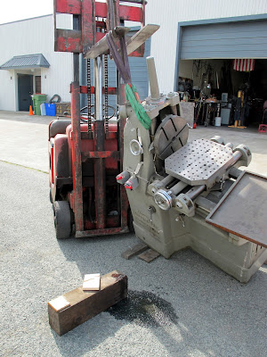
This is the sight that greeted me when I walked up. Not the worst rigging boo boo I've seen but definitely disappointing. Nobody got hurt and the only damage was to the machine itself. There were some long faces and a note of defeat in the air.
The ancient 1941 Towmotor forklift just wasn't up to the task. Apparently the rear wheels were lifting off the ground when they tried to lift it onto the trailer. As it tilted despite the effort of two guys acting as additional counterbalance the oily machine slid off the bare forks and flopped onto the tongue of the trailer. First things first. We had to get the machine stood back up and then discuss what the game plan was from that point to get it on the trailer. Machine is a WW2 vintage Kearney and Trecker Autometric Jig Bore and Layout machine Model A. Found the weight later on the web at ~3000 Lbs.
The little towmotor could handle the up righting since it didn't have to lift the entire weight of the machine. Some strategically placed dunnage keeps things from getting out of control in the opposite direction. The forklift is a cut down version of a full size lift and is used to drive into the backs of trucks to unload them. It only has a few more inches of lift left in the picture above. With some short slings we were able to rig it around the casting and lift it from there.
The forklift was a real gem. No throttle control at all with the sticking Zenith carburetor. Fast idle was all you get. If you accidentally stepped on the throttle you got stuck wide open and have to manually pull the butterfly closed. The side cover on the engine compartment was left off for just this reason. Gee don't you think you should take a look at the carburetor and see whats wrong? At least the brakes worked on this one unlike the Yam adventure. We were able to stand it back up without any rigging excitement. I headed back to the shop for some additional wood blocks and tie down chains with binders for the next challenge of securing the machine on the trailer.
Back standing up the way it belongs on proper blocks. Everybody is starting to feel better now. Unfortunately the tired Towmotor was not up to the task of getting the machine on the trailer. On the drive over  I noticed a steel shop down the street using a larger forklift to move steel around in their yard. I suggested they go and negotiate with the owner to borrow or rent the lift for a few minutes to get the machine on the trailer.
It sure pays to have the right tools. Harold was able to negotiate a forklift and the operator. This forklift made short safe work out of getting the dinged jig bore on the trailer
Next hitch in the deal was the rental trailer. It was intended for moving wheeled equipment like bobcats and ditch diggers, not jig bores. It had a four inch lip all the way around preventing us from placing it directly on the deck of the trailer. We had enough blocks to raise it to clear the lip of the trailer and allow the forks to come out. The operator was experienced and confident making it a pleasure to work with him.

The Towmotor had one final task in this adventure. We had to adjust the tongue on the trailer to get the ride height set correctly. This required an adjustment to the hitch height. Because of the single axel and size of the trailer we had to load the machine much too far forward on the trailer. The tongue weight must have been pretty good judging from the tail end of the pickup.
We used the forklift to lift the tongue up instead of hand cranking the wimpy jack mounted to the trailer. As we were hooking up the trailer to the truck my neighbor says he has decided he doesn't want the machine any more.???? Apparently he got it for free in what I assume to be working condition. Now that it needs some work to get it back together he has lost interest in the project. As a gesture of appreciation he offers the machine to me. Whoa. Can I think about it for a bit? Sure he says, you have two and a half miles to make up your mind. If you don't want it its going to the scrapper.

I'll give you two guesses what I said and the first guess doesn't count.
 Nothing like a new machine dropping out of the sky into your lap to put a smile on your face.
The Hyster barely noticed this pipsqueak machine balanced out near the end of the forks. Nothing like the right tool at the right time.
With the machine safely inside the shop I surveyed the damage from the rigging mishap. Fortunately the damage appears to be mainly cosmetic. Closer inspection may reveal something else.
 So far its looking like a couple of busted handwheels and some gouged paint. Not bad for an afternoons work.
Harold says he has more stuff that goes with the machine that he will drop by. I can hardly wait.

Thanks for looking.


Wednesday, February 13, 2013

Heavenly Repair

My antique restoration guy dropped another small repair off in the shop. He finds this broken junk in the dusty corners of Europe and brings them back for repair and resale here in the states. Apparently religious items have their own special export classification and are taxed accordingly. Instead of calling this item a religious item he lists things like this as "advertising" I got a kick out of that one.

If I do a bad job on this repair I'm going to mechanics hell. In mechanics hell everything is broken, dull and overheated. You cant find any tools and all your co-workers are real whack jobs. The machines need repairs every time you use them and nobody has cleaned them for an eternity.
Here is the job. If you look closely you can see a couple of the floral features got snapped off from dropping or during shipment. One is missing from the upper section and another is missing on the opposite side near the base.
The dealer had a decent idea as to how to fix it. I was thinking about how I might copy one of the floral features to replace the missing two. His idea was to remove one from the bottom and add it back at the top. His thinking was the upper part is more important visually than the bit near the base. I had to agree partly because it would have been a pain to make a new one on the cheap.
Here is where the replacement is coming from. All I need now is my handy amputation saw......
I need to cut the segment off so there is enough to make up for the lost piece and not come up short.
Just propping the item up to work on it is important. I need to hold on to it so the work can be done, but I don't want to introduce any new damage or problems that will have to be corrected. Preserve existing features and finishes as long as possible. This work was all done with hand tools. My only compromise was a battery powered Dremel that I tried to use to blend the stump of the amputation with. It turned out that a file worked better.
The tape is to protect the rest of the cross from any bozo slips or trips. The broken end of the floral needed to be flattened and cleaned up to make a strong joint with the graft. I decided to use a peg or dowel to strengthen the joint. My original plan was just to solder the two parts together but on closer inspection there was not enough joint area to make a sturdy soldered connection.
Using a pin vise I tapped both halves of the joint 0-80 to accept a set screw. The set screw will act as my dowel to fixture the joint and add strength.
Tapped and ready for soldering. The clocking of the joint wasn't a problem with the tiny screw. I was able to turn the assembly into alignment without over or under tightening the joint.
Trial assembly. I need to clean everything well just prior to soldering. Alignment looks good and there is a little room for the solder to get into the joint.
After the soldering the cleaned up joint really stands out. Unfortunately the nice patina needs to be removed to make a decent solder joint but stands out like a smashed thumb. I draw the line on any restorations at re-patinizing. To me this is where deception starts to enter the discussion.
The job came out well. The eye does not even focus on the lower section. The upper section definitely looks better and symmetrical.  Hopefully the bosses up in the front office think its serviceable.

By the way. If you go to machinist heaven all the tools are sharp and in the right place. The machines are pristine and self cleaning and use the finest espresso or single malt scotch as coolant. The tool crib has every tool ever invented in duplicate. All your co-workers are angels and bring homemade gourmet snacks in everyday and your feet never hurt from standing on concrete all day long because your in the clouds.

Thanks for looking.

Saturday, February 9, 2013

Copper Table Face Lift

I ran across some pictures of a small job I did a while back to resurrect an old oak library table we found. We found the table at a local consignment shop near our place for a reasonable price at a time when we needed a new kitchen table. On closer inspection the top surface was pretty beat up and would take a major effort to re-veneer or restore. The veneer was peeling off and the corners had seen better days. The legs and drawers were still in solid shape making it a good buy to spite the top surface. The legs are quarter sawn oak or at least have good oak veneer. The table itself is fairly heavy for its size so I pretty sure it didn't come from Ikea. It looks like a government issue library table. The only thing missing is one of those old solid oak office chairs.

A few years ago I read an article on the antimicrobial qualities of copper. Copper is also one of my favorite materials to work with. It warm rich color and smell remind me of the sheetmetal shop. We bought the table with the plan of skinning it with copper sheet. This would cover the beat up top surface and look architecturally cool. We hauled the table home and started making some calls to buy a sheet of thin copper for the top. I ran into a problem right out of the gate. Most copper sheet comes three feet wide and we needed thirty seven inches plus the return for the edges. Opps. I figured out an alternate way to do it with the narrower sheet but it was not what we wanted. Having an additional seam right where your arms sit was not what we had in mind. After calling all my copper contacts I still came up empty handed.

On a whim I checked Craigslist. To my surprise there were several listings for copper sheet. This was around the time that copper scrap prices were going up rapidly so people that had been sitting on some material were cashing in on the high scrap prices. A week later I checked again and somebody had a listing for a full ten foot that was sheet four feet wide. Suspicious after talking to my normal metal suppliers I questioned whether the person listing the copper had mis-measured it or maybe it wasn't even copper. After a couple of email exchanges I decided to go and at least have a look. Too late he told me somebody else was on their way to get the sheet. Dang! One thing about Craigslist is you have to move fast.

A few hours later I get a call that the buyer still hadn't shown up and If I wanted it still to get down there quick. I jumped in the truck and got going. I think you know how this ends. Yes, I got the sheet. It really was four feet wide and honest to god copper also. I asked him where he got it and he told me he worked at a metal supply place and he bought it for a project that never got going. It turns out the supplier he worked for is one of the places I called????? Still have not figured that one out yet.
My Kett electric snips made short work of the long cuts. In this shot the corner notches are ready to be snipped out with hand snips.
Flattening the corners after cutting the corner notches. The hammer face is UHMW plastic. This copper sheet is .027 thick. Since I don't have a sheetmetal brake yet I had to form the bends by hand with a slapper.
A slapper is just a broad faced hammer. Typically there are two types, soft faced and hard metal. For this application we don't want to stretch the material so soft face is the right choice.
A shot of the leather cover on the widest soft slapper I have. I couldn't find any pictures of the forming operation for the actual table cover so I set up a short demonstration piece.
The forming operation uses the table itself as the die to form the inside of the bend. The board is just a broad clamping surface to keep the unregistered blank from shifting during the slap bending. On the table I formed two bends adjacent to one another to anchor the sheet and accurately locate the opposite side bends.

The trick with slap bending is not to get greedy. What I mean by that is just form a few degrees the full length of the bend at a time. Go back to the start and form a few more degrees each pass until you reach ninety degrees.
Use the slapper as a broad faced hammer. Aiming to contact the length and width of the slapper to the material at the same time. Sometimes a glancing blow is an easier way to make that kind of contact hit. Rotate your clamps to access the material close to the clamp. Don't remove any clamps if possible. The bend can migrate back under the clamp board if you remove a clamp or don't have enough clamps.
Keep working the bend over until you reach ninety degrees. There will some spring back will all materials. The softer the material the less spring back.
Almost there. I did this demo bend in three passes to get to ninety degrees.
Ninety degrees. The technique I just described is what I used to make the bends on the skin for the table.
Before I made the edge return bends I punched holes along the edges so we could use tacks to secure the top to the table. It was a visual detail to make it have more texture and look like an old time steamer chest.  It took a while to layout and punch holes on one inch centers all the way around the table. My first Idea was to just drive the tacks through the material without making a starting hole. A quick test showed this was a really bad idea. As it was there were some pinched fingers driving all those tacks into an oak table.
We added some corner covers to hide the un-welded seam. You can see the copper tacks we used to secure the top to the table. These had to be smoothed because your arms and hands bump into the heads of the tacks. A scouring with Scotchbrite deburred them enough so you don't notice them with your arms and legs.
We like the cover. Certain foods stain it some but its easy to clean. You quickly give up on keeping it polished all the time. In the winter is cool on the arms if your like me and didn't listen to your mom about no arms on the table while your eating. We ended up getting some place mats to keep the elbows warm.

Thanks for looking.

Thursday, February 7, 2013

Mice have left the barn

After many months of difficult work and re-work the MICE coupling coil finally shipped. It was good to see it go out finally ready for testing. I wrote a couple of  articles about the work we were doing to the coil in anticipation to shipping to another facility for cryogenic testing.

At the end of the last article I mentioned we were nearing the final stages of completing the mechanical and instrumentation tasks needed for testing. One of the last operations needed to certify the coupling coil for testing was to leak check the cryogenic cooling tubes that wrap around the circumference of the coil.

The cooling tubes are heavy wall aluminum 6060 alloy. For this particular application this was the only available alloy in the correct metric size. In fact I had to look up this alloy so I could figure out what the differences are from the more common 6000 series aluminum alloys. There were some tricky forming operations required for these cooling tubes. A custom bending die was fabricated to form a tight bend in the tube near where it entered the reservoir box at the top of the coil.
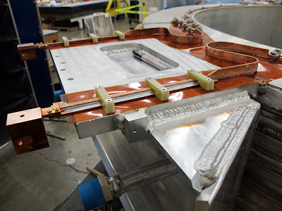
This is the heavy aluminum helium reservoir box. The cooling tubes make a tight bend to come from the circumference of the coil and emerge in the box where they connect to the helium system. This is where our big problem turned out to be.

During leak checking we discovered a very faint leak near the bend in the cooling tube. The leak was in the area close to where the tube entered the box. This made any attempt at repair difficult at best. The first repair attempt was to try to weld a patch over the suspected area to try to seal the leak.
I couldn't release it for shipping without one of the project managers signing off on it even though the leak we detected was extremely small. To put the size of the leak in perspective its something like one milliliter of gas through the leak per hundred years at standard pressure. The main concern was how the leak would behave when the coil was cooled off to superconducting temperatures, in the case of this magnet that's 1.9 Kelvin. Weird things happen at two degrees above absolute zero. Nobody wants to take any chances.
A couple of shots of the cooling tubes. They are fully welded around the circumference of the magnet coil. This improves conductivity between the tubes and the coil. To avoid softening the tubing excessively the welding interpass temperature was specified to be less than 150F. Even with all the special precautions we still ended up with a leak. But this is why we check these things. Trust but verify.
Here we are running nitrogen through the cooling tubes to dry any moisture out before we leak check. This is done to get the base pressure of the tube low enough to detect the tiniest leaks. On the right side of the picture is a gas heater that warms the gas coming off the nitrogen dewar before it circulates through the magnet cooling tube.
In this picture we are set up to leak check the tube. The vapor is liquid nitrogen from a cold trap that is protecting the leak detector from back streaming any junk from the tube. Unfortunately the patch didn't work and we had to come up with another plan to repair the cooling tube.

This magnet is part of a large international collaboration project. We did much of the assembly and instrumentation but lacked a cryogenic facility large enough to cool and test the magnet. This magnet will be tested in a gigantic cryostat at Fermilab in Illinois as part of this collaboration. During the repair there were many back and forth discussions on how to repair the leak, and follow all the necessary safety requirements of multiple institutions. The document trail on this project could reach all the way to Illinois if you laid the pages end to end.
After much discussion and planning the solution was to perform the equivilant of a heart bypass on the cooling tube. You can see in this picture how far we went trying to chase the leak in the tube. A lot of the removed material was just to provide access for the welding team to get to the area's that needed welding.
Finally the bypass was complete. The collaboration had decided that the tube needed a pressure test as well as a vacuum leak check. More discussions and back and forth with safety requirements. Eventually we performed a pressure test by filling the tube with water and pressurizing it to the required stress level for the test. One thing we don't mess around with is any safety requirements on jobs like this.
This is a good shot of the amount of welding needed to put this magnet together. Check out the gigantic MIG weld at the top of the casing. There is something like 85 Kilometers of superconducting wire wound around this glorified sewing bobbin.
At last we get to the final stages of the job. This is the final pressure test of all the cooling tubes on the magnet. The engineer in charge is smiling because it going according to plan and nothing is happening, just the way he wants. The more sensitive test is the final vacuum leak check after the pressure test. Just in case we stressed the tubes and inadvertently caused a new leak.
The pressure test setup from the reservoir box side. We installed a pressure relief valve to protect the tube from any possible overpressure situation. We filled the tubes with water and pumped the tube up to the test pressure in increments, holding at each pressure for ten minutes. You would swear the clock slows down when you have to time an interval like this multiple times. See the document on the table. That represents over two man months of work for the project mechanical engineer. This is a time when I'm really glad to not be a an engineer.
Not much danger of overpressure with this hand pump. The test pressure was close to the maximum this had pump could put out. You would have had to jump up and down on the lever to get the pressure to spike with this setup. All the tubes held pressure with no leakdown over the ten minutes.

So the coil finally passed all the pressure and vacuum requirements. We were released to package the coil for shipment to Fermilab. The project engineer was pretty happy about this. He got a wonderful weather day to finish the job.
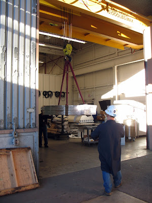
 The finished magnet weighs around 4000 lbs. Easy work for the assembly shop crane. Now is not the time to bump into anything. Ahmet gladly turned the crane controls over to me for this part.
Almost there. Behind me is one nervous engineer. He was visibly relieved when the magnet touched down in the crate.
We installed a bunch of these shock watch sensors on the crate and directly on the coil to monitor the shipment. On more fragile items we install an active accelerometers to the item that log the entire journey end to end. If there is a problem we can see when it occurred and the magnitude.
This is the end of the story for me. Its in the box and belongs to somebody else now. It was a challenging and interesting problem. Hey, if everything went perfect it would have been boring.
Five days later its back out of the box at Fermilab. The shockwatches on the crate were all tripped but the ones on the magnet were fine. The crate had it own special suspension system to cushion the ride across the country. Worth the extra cost for the crate.

Thanks for looking.