Tuesday, June 25, 2013

Machining Small Angles with the Tilt Table

Last year we were faced with a tricky angle machining problem. The job was to machine some very small angles into an existing part used for precision alignment. Some background is in order to explain why we needed to machine such small angles.

Recently we built a linear particle accelerator to shoot lithium ions into a metal foil target to study warm dense matter as part of fusion energy research. In the heart of the accelerator are a series of high field pulsed solenoid magnets spaced apart along the length of the accelerator. These magnets are used to shape and kick the beam as it moves along the machine. For the function of the machine these magnets (27) all had to be very accurately aligned to one another and to the machine as a whole.

To compound the difficulty of aligning these solenoids they are inside an atmospheric pressure chamber buried deep inside a high vacuum chamber. Alignment, or even adjustment of the magnets after the machine was assembled would be impossible.  The only choice was to align the magnets accurately prior to sealing them up inside the machine.

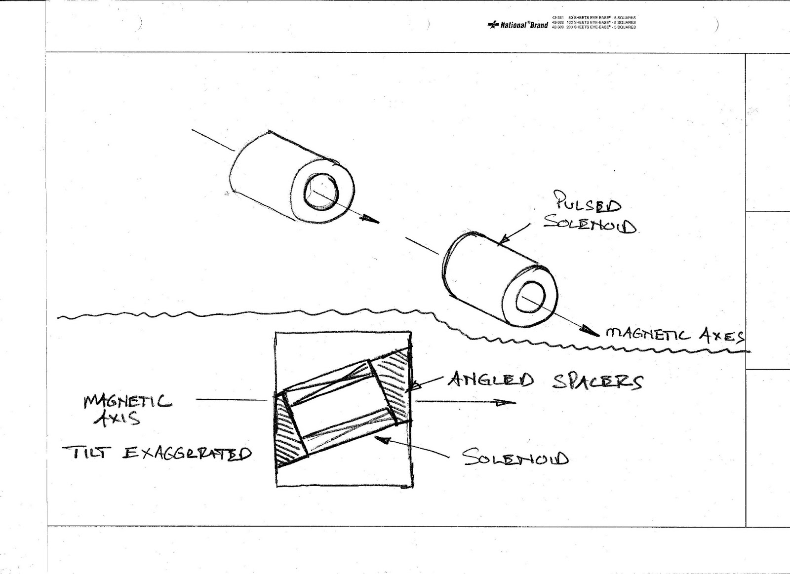
To start the process we built a special machine to measure the exact center of the magnetic field of each of the magnets before we sealed them up inside the machine forever. During winding and epoxy potting of the magnets small tolerances stack up to make each magnet somewhat unique. Each of the magnets was installed in its own special housing that also had small differences adding to a system error or offset. The magnet measuring machine uses a stretched wire that passes through the solenoid opening. The magnet is pulsed during testing which caused the wire to vibrated with a waveform we can analyze. The wire can be moved in space until the exact magnetic center is found nulling the vibrations. The basic problem is the magnetic center is not necessarily at the same position as the mechanical center of the physical magnet.
Now here is the trick part. Because we know where the wire is precisely, determined by using a laser diodes and micrometers to sense the wire. We can now transfer those measurements to the physical part of the support structure that houses the magnets and align the magnet accurately to the structure. Over forty feet our alignment target was a cylindrical tube shaped tolerance zone one millimeter in diameter. When I describe the problem to non technical folks I ask them to imagine aligning 30 individual pencil in space in almost all spatial orientations X, Y, Z pitch, yaw with a foot between each pencil and have them place a dot on a piece of paper within a circle one millimeter in diameter.

Each magnet had to be aligned to a angular tolerance of ten milliradians or less in tilt and less than 30 microns in X and Y. To provide alignment adjustment there is a system of flexures that are used to align the magnets for tilt and XY displacement. All this is pretty straightforward until you find out there are large magnetic forces axially along the solenoid axis when each magnet pulses. This force was calculated to be around 900 lbs.
Here is where our machining problem comes in. We needed end spacers to trap the magnet axially in its cavity to prevent it from moving. The spacers needed to be accurate in thickness and have a very specific angle machined into them to match the tilt error of each solenoid and housing. To make it even more interesting the spacers were round to fit the end of the solenoid magnets. What this added to the mix was a radial orientation that had to match.
To do this job we used a special tilt table that I built many years ago. Angle setups are among the most difficult and demanding jobs that most machinists encounter. If your angular setup is not perfect the results will be sub-optimal. I personally use the sine bar for many of my angular setups because they are easy to use and very accurate. In the case of these special spacers the angles were very small, on the order of one tenth of a degree. The sine bar can easily handle small angles like this but the work holding part of the job made it a better job for the tilt table. One problem with sine bars is the limited options for mounting parts directly to them for machining. Somebody out there invent a Kurt vise that has sine rolls built into the bottom and a good way to lock it to the table for real machine work.

The scientist taking the measurements gave us the angular data as a dimension over a distance with a radial clocking reference. So we might get numbers like .015 inches over the diameter of the spacer which was 8.5 inches. Saying it another way is .015/8.5 which describes the angle enough for machining. Using the tilt table its a simple matter to set this angle using a dial indicator and a parallel.
The angle is set by traversing along the parallel a fixed distance (in this case 8.5) and noting the indicator displacement. The angle is adjusted by turning rest screws that bear against the top of the vise.
In this shot you can see how the tilt table works. A steel rod is attached to the table working surface and clamped in the vise. The table can pivot on this rod to angles up to around fifty degrees from the horizontal. Obviously the rest screws will not touch at those high angles. There are a several ways to set an angle using the tilt table. In addition to the method above using an indicator to measure along a fixed distance angle blocks and  electronic levels can be used depending on accuracy needs.
In this shot a fixed angle block is being used to set the tilt table angle. The angle plate can be substituted for a small sine bar.
The underside of the tilt table showing the clamp and pivot rod attachment to the plate.

Setting a quick angle with an electronic level. This particular level has the ability to re-set the origin on any reference surface.

Because the top surface of the tilt table is festooned with tapped holes I can use it with the mini pallet strap clamps for a variety of workholding options.  I find it most useful for longer low angle work such as doctor blades or single bevel cutting edges. The table is most stable  when set to a low angle and its long clamping surface provides lots of holding options for the work.


Thanks for looking.


Sunday, June 2, 2013

Heavy duty lathe steady rest

Recently I started a large (secret) project for my wife that will take the better part of a year to complete. Right away I realized there were some missing infrastructure items that would be required that would be hard to built right in the middle of the larger project. The first tooling deficiency I ran into was my lathe steady rest.

The large Yam lathe I bought last year came with a significant amount of tooling. A three point steady rest was one of the tooling pieces. Initially everything looked pretty sweet. My large secret project has need of several long large diameter shafts which is one reason I chose this particular lathe. I figured get the big Conan lathe first and hold out for the sweetheart deal on a really nice smaller lathe when it appears in my machinery shopping sights.

During the secret project design phase I made a decision that was connected to the lathe acquisition. Since it is so long I decided to increase the basic size of the project considerably. Hey, if you're going to go to the trouble and expense to build your own secret project then go for the gold medal. Who the heck wants a bronze anyway?

So it turns out the steady rest that came with my lathe is way too small. It can pass 7.85 through the frame and I need to pass at least eight inches through. So this is how a tooling project is born. A steady rest is a pretty straightforward project in a machine shop. There is nothing too fancy or critical to the proper functioning of a steady rest so if your lathe is missing one I encourage you to go ahead and make one.

First order of business was to take some measurements of the stock Yam steady rest. The only semi important number is the center height off the ways. From these measurements its easy to develop the larger size I need.
For the new steady rest I wanted anti friction roller tips instead of the bronze tips that the stock Yam unit has. I figured if I was going to build one I'd make it slightly different and better just for good measure. Roller tips mark the work less but have a nasty habit of sucking chips between the roller and the work. Non rotating tips generally don't allow chip between the work and the rip but at the the expense of marking the work more and with higher friction. Its a common and simple enough matter to make a thin plastic shield to keeps chips from finding the roller tips.
Measuring the vee way depth on the stock steady rest. I got lucky that it was a ninety degree angle instead of some oddball thing.
The large steady profile was cut from the electronic layout you see above. Material used is one and a half inch thick steel plate. I added some extra material in the center and at the bottom so I could cut the profile in half and still clean up the machined surfaces and end up with a proper circular opening.
Check out the awesome oxy fuel cutting provided by Nowell Steel in Antioch. These guys do all my heavy steel cutting. Talk to Ted or Chris if you need some steel cut.
I scribed the base block directly off the stock steady rest. This was just for the roughing of the vee groove. Once I was close I started taking measurements for precision depth.
When the groove was shallow I had to use my multi-anvil micrometer because the pin was above the surface. These handy versatile micrometers have the ability to measure from a flat surface up as well as a multitude of other measurements. Once the gage pin was below the surface of the block the normal depth micrometer could be used with more stability.
I used the trusty Doall vertical band saw to split the profile. It took about ten minutes to make the split I left material between for machining the ears to thickness after the saw cut. I still have to make the latch and hinge for the two halves. All the time I was sawing the profile I was wondering which way it would spring. This is one good reason to cut a profile as a closed shape. In particular if you use a heat producing process. If I would have waterjet cut this I most likely would have cut them as halves with a small amount of material for machining. On this thickness of material the oxy fuel process is faster and cheaper. My time is free in my shop.
This is the clamp plate that secures the steady rest to the underside of the lathe. The bolt will pass through the bottom of the steady rest and be tightened from topside.
This last weekend I worked on the roller guides. There was quite a bit of work in these puppies. Early on I thought I wanted a single side support with a stud type cam follower. I was looking at one of the lathes in the main shop the other day and it had a very nice roller setup on its steady rest. The lathe was a Cazeneuve. Once I decided to make the support double sided it doubled the amount of work in these parts. My milling machine looks like a steel sliver bomb went off near it.
 The axels for the cam followers are made from the hardened shanks of shoulder bolts. The shaft is clamped in the roller support tightly for minimum vibration.

I have been documenting the build with video. Check out the Oxtoolco YouTube channel if you want to see some live machine shop action on this project.

Thanks for looking.