Sunday, September 30, 2012

Superconducting Magnet Preloading

Last week we finished the preloading of our next test magnet HD3. HD3 is a dipole superconducting magnet with a 50mm through bore. It is part of our continuing base program development in increasing field strength and quality while evaluating new materials and construction processes. The preloading process is interesting because of the large size of the magnet and huge forces involved. This magnet is constructed of Niobium Titanium superconductor cable and is only superconducting when it is at very low temperature below the boiling point of liquid helium (9 Kelvin). At this low temperature the electrical current passes through the magnet without any resistance or losses.

HD3 is a dipole magnet which means it has two coils. These coils want to repel each other pretty vigorously when the current is flowing in the magnet. Field strength for HD3 is probably on the order of twelve tesla peak field. To help quantify what a Tesla sized field is one of the little high power neodymium magnets everybody has played with is about 1.25 Tesla right at the surface. If you have messed around with one of these magnets you know just how strong they are. HD3 our big superconducting magnet has a field strength an order of magnitude larger. What's the big deal right? Its only ten times stronger. Well here size and surface area do matter. HD3 weighs over two tons when it goes into the cryostat for testing. The forces inside the magnet are massive. Imagine a refrigerator magnet that weighs two tons and has a field ten times what one of the little finger pinching magnets you played with. In fact it would pull your refrigerator through the wall instead of sticking your shopping list to it.

One of the problems with superconductors is they really have to be coaxed into doing it. We have to treat them nicely and give them a perfect place to sit and a maintain the perfect temperature. The slightest amount of heat or movement and they quit superconducting. We call this a quench. This is when a superconductor quits carrying current without resistance. Its a problem when you have a dozen or so megajoules of energy running around inside the magnet when it quenches. Our test facility has an elaborate system to deal with the large amounts of liberated electricity when one of the test magnets quenches. One of the primary causes of quenches are tiny movements within the magnet itself. Something shifts or settles and these movements cause a tiny local heating which induces a quench. One of the ways we prevent mechanical movement and shifting is by careful preloading of the magnet at room temperature.
In this first picture the coil pack is out of the main magnet casing during the assembly process. You can see the gold colored leads coming off the two coils. These coils are wound similar to a racetrack but with the ends kicked up to improve the field at the ends of the coils. During this assemble step the coil pack is being squared up and measured. The trapezoidal plate on the top with the two holes is one of the load pads that transmit the preloading forces to the coils underneath.
 In this picture you see a single coil before it is put face to face in the coil pack. Note the down "kicked" ends where the coil winding is out of the normal racetrack winding plane. The wound coil is vacuum impregnated with special epoxy to keep it mechanically confined and insulated.
Here is a picture of the new coilpack measuring gage in use. We take measurements along the load pads to make sure the starting position of the coilpack prior to loading are parallel and perpendicular. Some of the other wires you see coming out of the lead end of the magnet are instrumentation and voltage monitoring leads. Each coil is instrumented with strain gages and voltage taps that are routed out of the magnet and cryostat to the outside world.
 One of the strain gage stations on the inside of the bore of the magnet. There are two sets of each direction gage. One set is floating so we can compare a gage under the same conditions that is not under mechanical stress so we can determine how much force we see from magnetic and mechanical loading. Kind of like a calibration standard.
I don't know how the electrical engineers keep track of all this wiring. It always looks very mad scientist like just before a magnet test. Somewhere in there is the strain gage and voltage taps wires I mentioned.
 This picture shows the coil pack inserted into the magnet structure and outer aluminum shell. You can just see the load pad that I mentioned earlier on the right. The two axial loading rods pass through the load pads and help in preloading the magnet in the axial (long ways) direction. You can see this is all in a pretty tight package.

When we preload the magnet the idea is we load it to some nominal level slightly higher than what we expect to see when the magnet is under test. This pre-stressing is crucial to preventing movement and resisting the magnetic forces that want to make the coils fly apart from one another. The first step in loading the magnet is to apply some compressive force to the coils. How do we do that?
The process is called bladders, shims and keys. If you look in the picture above you can see the end of one of the bladders near the blue tape D2. The small stainless tube connects the bladder to a high pressure pump. Basically like a metal balloon, the bladders are made from thin stainless sheet and laser welded along the seams to seal them into a closed vessel. We pressurize them with water at high pressure to compress the coil assembly. To keep the pressure on the coils we insert keys and shims to take up the space during pressurization. Sort of like jacking your car up with a hydraulic jack. You pump the jack a bit and then put a block under the car to hold it up. You can now let the jack down but the car stays where the block is holding it in position.  This is similar to how we preload the magnet.
In this picture you can see the high pressure pump and hoses leading to the bladders inside the magnet. We carefully pump the bladders up and insert shims to maintain the preload on the magnet. It is a step process where we go up in small increments until we hit the desired target preload. All of this is with direct feedback from strain gages mounted on the coil windings and the aluminum shell of the magnet. As we add load to the magnet coils the stress in the aluminum shell goes into tension from the internal pressure. Much like a high pressure gas cylinder.
Another shot of the high pressure tubing connections to the bladders. Typical bladder pressures are in the three to five thousand psi. We have gone as high as ten thousand psi but not on this particular magnet.
This is the lead end of the magnet. We added a couple of dial indicators to monitor how much the two load pads move relative to one another during the loading.  After several rounds of pressurizing and shimming we arrive at the target load. This is derived from the strain gage readings of the stress on the coils and shell.

The final step is to load the magnet in the axial direction using the large threaded rods. We don't actually crank the nuts down to apply the force. This is also done hydraulically and the nuts taken up to maintain the loaded position. With strain gages mounted on the rods we can more accurately preload the rods than by turning or torquing the nuts.

So all of this is just preparation and pre-stressing the magnet before we cool it down to 4.2 Kelvin. Most people know that when you heat something up it expands right? What do you think happens when we cool the magnet down? If you guessed that it shrinks you are correct. In fact we are counting on it here. When the magnet cools it shrinks considerably which is the final part of this operation. The aluminum shell that houses the magnet applies the final loading after cool down. Aluminum expands and contracts at a higher rate than the steel structure inside. This is called the coefficient of thermal expansion shorthand CTE. For each degree of cooling the aluminum contracts almost twice what the steel does causing a constricting force all the way around the magnet. If you do the math the shell shrinks around an eighth of an inch just from the cooling. It is acting like a really expensive hose clamp that holds the two magnet coils from moving when it is energized. 

Tuesday, September 25, 2012

Hyster Hydraulic Cylinder Straightener

As I work on the new forklift I keep finding new things that need attention. Looking at the front end near the forks I discovered I had a bit of a problem. I noticed that the two hydraulic rams that move the forks in and out were pretty badly bent. It looks like somebody bumped into a load that was sticking out a little and hit the rams when they were extended near their limit. Scale wise these are pretty small rams with .75 diameter rods for the cylinders so the fact they got bent is not really shocking. Think about a 12,000 lb forklift bumping into a small rod, I'm sure they didn't even feel it.
In this picture you can see how the rod is bent pretty badly. It was a minor hassle just to get at the rods so I could do something about it. My goal was to not remove the cylinders from the machine so I wouldn't have to deal with hydraulic oil and the more major disassembly needed to get them physically out of the front rack. Everything on this lift is really heavy. The forks by themselves probably weigh three or four hundred pounds each so you have to move slowly and use  mechanical aids like jacks and come-alongs to move things.

After looking the problem over I decided to make a tool to try to straighten the rods in place. I needed to generate a large amount of force in a small package to get it in around the rod at the bend. The rod was only .75 diameter but is probably made of 1045 or 1050 steel and induction hardened like most chrome plated hydraulic rods. Fortunately the rods had no scars or kinks in them that would make this an tough fix. I started thinking about how I could generate the necessary force to yield the rod in place. A quick calculation of the bending stress needed to bend .75 diameter 80Kpsi steel told me I needed to generate something on the order of 2 tons of force in the space I had to work with to get the rod to move. It would be simple to generate that kind of force if I had a small hydraulic ram and a pump, but I was out of luck. I ended up doing it mechanically.
Here is my first concept sketch of the bender. It is an eccentric device similar in principle to this one. Eccentrics can generate some pretty high forces in small packages. The trick here was a little human was going to have to turn it and make it go.
After a trip down to the shop to see what I had on hand to make this thing with I came up with some similar parts that had most of the ingredients. I went back and re-sketched the design based on what I had lying about.
Second pass on the design study. I have added the sizes of all the parts so I could model it up in Solidworks. An eccentrics force is related to its position during rotation. In fact the forces go to infinity just at the point of going over center much like a toggle or knuckle press. My problem was I needed to deflect the rod enough to get it to yield. Another calculation told me I needed to move the rod only .015 inch to get the necessary force. That number assumes quite a few things and is related to simple beams and felt a bit small to me intuitively. This entire device would deflect under load and I really was really just guessing at the yield strength of the rod. In this case better to have a some extra travel than not enough. I decided to leave a space between the eccentric and the rod that I could make up with sacrificial shims. The shims serve two purposes. One, they allow me to make up the space between the rod and eccentric so I can get the eccentric aligned at the perfect spot in its travel to generate a large force. Second, the shims would be used to protect the hydraulic rod from damage from the eccentric rotation. 
After modeling the straightener up in Solidworks. Note the space between the eccentric and the dummy rod.
Time to get busy in the shop. This is the baseplate showing the eccentric pivot hole and the rod support holes. I'm using a Hougen Rotabroach to make the holes. These make fast work of holes in steel. Accuracy is really good and more than enough for this Sunday project.
Cutting the eccentric pivot material on the vertical bandsaw. The upsidedown vise is a great handle and keeps the rod from spinning when you engage and exit the cut. The plywood is a belly board so I don't have to push so hard with my hands close to the blade. Safety first with fingers.
Welding the blank bushing into the base plate. The pivot boss is 8620 steel and the plate is just A36 hot rolled plate. Its all I had around on short notice.
Boring the bushing to size after the welding. I left a little material sitting above the surface of the plate to make a nice surface for the eccentric to pivot on.
Boring the offset in the eccentric. You can see the .25 inch offset from center easily in this picture. I am boring it to fit the head of a large socket head cap screw that is my main pivot shaft. At this point I'm wondering if I have too much eccentric offset.
Almost finished eccentric. I needed to add a good way to drive the eccentric with a lot of torque. I ended up just welding a large nut to the top of the eccentric to drive it.
Here are the rod supports being machined. I cut a shallow saddle into the head of the screw to protect the hydraulic shaft from serious point loading. Originally I envisioned these pivoting to allow for the angle change during the bending but theory ran smack into reality and I had to just fix them in position.
Here is a bench test of the bender. The rod in this case was just some cold rolled steel with a low yield point. You can see the copper shims have seen some serious force even for this fairly soft rod. Hey, at this point I'm pretty happy that it works.
So far so good. The rods are some strong stuff. I had to add a length of pipe as a reaction bar to crank on the eccentric. The copper was totally squashed and extruded like silly putty. I think the yield strength is higher than I guessed at.
Starting to look pretty good now. It was hard to turn the eccentric in the hot sun and get good pictures. I chose to get the rod straightened and let my limited literary prowess describe the process in words instead.
Not bad for a few hours of work. They are not perfect but the improvement is huge. The forks actually went in and out before the straightening even with the huge bows in the rods. The seal seem intact so I'm going to leave it for now and see what happens.

Thursday, September 20, 2012

Hundred year old switch

An electrician friend brought me an interesting repair job. I met Anne when she basically re-wired our entire accelerator project. Between her and one apprentice they ran something like three hundred different circuits to supply everything from 1200 Amp 480 down to dozens of separate 110 circuits and a couple of miles of conduit. All said and done three quarters of a Megawatt in power distribution in one room.

One day she brings me an antique electrical switch out of her old Victorian house. The thing is ancient and broken which is the reason for her visit. My requirement for a job like this is it must me interesting. This had all the elements of intriguing little diversion. Some forensic analysis, some tooling fabrication and some challenge.
This is what I had to work with. In this picture I had already removed the fried contacts from the switch. To get at the screws some ceramic or hardened insulator had to be excavated from the screw recesses. One was broken and the other was arced into submission. First step was to measure it up and make a decent drawing. I had to use details from both contacts to fill in all the features. If any more had been missing it would have made the job even more challenging.
True to form nothing starts out perfectly. After measuring the contact parts and making a nice drawing I was anxious to get started cutting the material. Anne makes these great oatmeal pecan chocolate chip cookies that I was thinking about when I got started. First stop was the precision nine inch Diacro shear. We save this shear for all the precision cuts on thin materials that we want to be burr free. I have cut one and a half thou tungsten foil on this shear perfectly. Its only problem is it lacks a decent back gage. I have had an idea in the back of my mind but no time to execute it. We guess what, this was the time. It was pretty easy to do since I had ninety percent of what was needed already squirreled away.
Not super high tech but it works just like I wanted. The switch contact blanks needed to be sheared accurately and they were only .475 x .700. The micrometer gives me easy adjustability to dial in the exact size. It was a small diversion and worth it for this job.Previous to this we would use the calipers to measure up to the blade to gage the cut. For blanks this small it really was a job for a backgage.
Ok second problem. The Dykem I had around the was pretty ancient. In fact it was so bad I had to dispose of it in our hazardous waste collection. The red cherry flavor was in better shape but not dark enough for my old eyes and the really light layout lines I wanted to use on this material. There were quite a few bends in thin material with no real bend radius. These bends combined with deep layout lines spells cracking. Good old Sharpie came to the rescue. I don't know why these guys don't make layout fluid. Its better than sliced bread and always in my pocket. Maybe I'll see if I can buy a pint of Sharpie juice to use as layout ink.Sanford, your missing a business opportunity here.
All the layout was done with small calipers. The blanks were so small using a height gage for the layout wouldn't work. I only needed two mirror image parts so speed was king. For little fussy things like these contacts always make a few extra blanks. Material used was .015 thick Be/Cu half hard condition.This material forms well and is commonly used for RF finger stock,  electrical contacts and springs.
Making the tiny notches with a hand operated Diacro corner notcher. The material is pretty hard and was thick enough to get a nice clean cut.
Final notching was done on the milling machine. The parts were stacked and clamped with my smallest parallel clamp which was a handy handle also in this case. The slot was just a shade over 1/8 inch wide. In this example I just milled to the scribe lines. If I had to make a large number of these without a die I might wire EDM cut them to preserve the heat treat and mechanical qualities. You could stack these pretty high in a WEDM and get a perfect profile.
The one hole in the contact was an odd punch size so I had to be drilled. Not my first choice on thin sheet grabium but I had no punches even close. I ended up center drilling them through first to give a solid starting point for the #32 (.116) drill. The large headed tack is an anti spin device and a hold down. If the part spun the tack would catch it and if the drill caught on retraction like they sometimes do, the oversize head would hold the part down to the backup wood and not bend it and piss me off.
All that just to get to the flat blanks for the contacts.Now for the fun part, the forming. I took a look at the small Diacro box and pan brake and decided it was not up to this job. On thin materials with sharp crisp bends your clamping and followers have to be positioned very tightly together. The Diacro is a great precision brake but not tight enough for this job. There were several bends close together in a back to back joggle and to further complicate the forming the two contacts were mirror images.
In this shot you can see the joggle and the small rounded return on the left hand contact. I made up a tapered Delrin caulking tool to help with the bend forming.
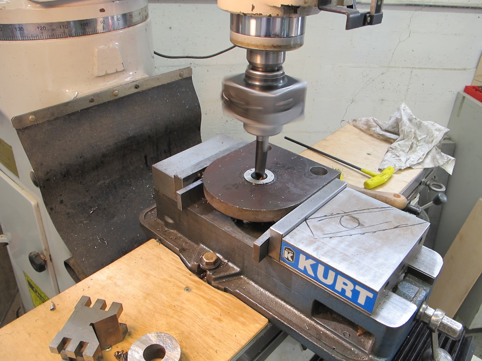
Here is my bending brake for precision parts in thin material. The smaller vise has hard jaws that are surface ground flush to the top surface of the vise with no steps or offsets. I stoned the inside of the hard jaw so it wouldn't act like a shear on the thin sheet. You can see its easy to work off either side of the small vise to hang already formed returns over to access the remaining bends. This whole mess is clamped in the Kurt vise on the milling machine.
  Starting the first bend. The Delrin caulking tool reaches right to the surface of the vise. This gives me a nice tight crisp initial crease on the bend. Additional angle is easy after the first crease sets the bend position.
You can see in this picture its easy to hang the part off the edge of the forming vise to clear the next bend. Measuring the small angles is the tricky part. All the bends here were ninety and forty fives nominally.
The last bend which is the lead in for the moving parts of the switch to engage the stationary contact. I think I lucked out a little on the bend sequence. Many times it pays to make a paper cutout to check the bend order so you don't back yourself into a corner.
All the bends are in. Now you can see what the old contacts might have looked like a hundred years ago. Next up were a few locating dimples for the mounting screw and a spherical dimple for the contact face.
A little hard to get a good picture. The dimple former is made from a 1/8 diameter dowel pin and ground to shape on a diamond toolbit sharpener. Final radiusing was done with a hand held diamond hone stick. This was held in a drill chuck in the mill and indented into a Delrin backer under the part. Delrin is hard enough to get crisp detail, be not so hard that the material get sheared or needs large amounts of pressure to do the forming.
The contacts installed in the switch. You can just see the the spherical indentations in the flats. This was also formed with a dowel pin shaped on the diamond grinder on a Delrin plastic backer. I didn't get a shot of the index bumps you see in the original but trust me they are there. A pretty fun job actually and I got the shear tuned up the way I wanted in the process.

Looking forward to those oatmeal pecan chocolate chip cookies Anne. Thanks for the fun forming job.

9-25-12 Update,
 Score!!!

Twelve Thousand Pounds of Love

One of my hobbies is I like to plant little machinery trees. I poke a seed into the ground every once in a while and occasionally put some water on the budding plant. If my little tree dies then there was nothing that could have been done to save it and I just plant another. This story is about a tree of the genus Hyster forklifticus. Where my shop is, is really a heavy industrial area. In the evenings I walk Ernie the shop dog around and see all kinds of interesting things going on at all times of the day a and night. A few months ago something caught my attention on one of my dog walks. Also, I might need to back up a little further to give some background to make the story more interesting.

A year or so ago I had a local company quote a special pressure vessel for the high pressure air system for the NDCX2 accelerator. We couldn't build it ourselves internally without a major safety and engineering effort, so for efficiency's sake we had it built by an outside vendor from a drawing we provided. One of the companies that quoted the job happens to be right down the street from my shop. I was thinking if they were awarded the contract I could easily visit and see it built and perhaps get a shop tour out of the deal. As it turns out I got the tour anyway before the contract went out to another vendor. If you need a pressure vessel built try Johansing iron works in Oakland. We were very pleased with their work.
I this detail picture you can see some of the offsticker we tap into the manifold with. When the vessel showed up the huge fillet welds on these couplomgd caught my attention. The vessel is rated at a MAWP of 250 psi. The hydrostatic test pressure was something like double that. Why did they use schedule 80 coupling and weld the snot out of them with these giant fillet welds? The answer is purely mechanical. I guess the guys that design proper pressure vessels have met some cro-magnon plumbers. The extra heavy couplings and extra weld reinforcement are so the fitting is not twisted and yielded during fitting installation. Easy enough to do with a two foot pipe wrench if you don't pay attention.

The shop that I toured makes special screw conveyors and is a certified pressure vessel fabricator that can stamp vessels to code. It happens that their main shop was used during WW2 and the Korean war for some very interesting projects. Below are a couple of pictures from the lobby taken with spy cam.
Looking out the main bay doors of the building they currently occupy back into history. Trains and flatcars would back into the building and have tanks loaded on them to shuttle them out to the waiting convoy ships. These bridge cranes are still used on a daily basis today. I walked the dog by there this evening and the shop was still humming even after dark. They must have a hot job going on to be working overtime.
In this shot I can see my building off in the distance. I would love to see what it was used for when this picture was taken. And this is where my little tree story starts.

Just out of this picture on the right is a little fenced laydown yard where junk and leftovers are put out to pasture. One day when I was walking the rat I noticed a forklift had magically appeared in the yard. I actually saw this forklift inside the main bay when I went for a shop tour. For the life of me I couldn't tell you why I remember it. Perhaps it was because it had the hood up and they were working on it and that caught my attention. Well this very lift was now in what looked like graveyard cold storage. How it was parked and the fact that the key was still in it made me curious about what could be happening to this forklift. Several weeks went by, then a month or two. It was pretty obvious that it had been put out to pasture. I always feel sad for machines that look like they have plenty of life in them sent and are sent to the glue factory. It just happens that I had been in the market for a lift for a while. The older I get the worse my back is and the more I eyeball material handling equipment. My hobbies aren't getting any lighter that's for sure. I have a big lathe in my near future and a lift like this could pay itself back on rigging costs alone.
Machinery etiquette says it would be pretty rude to just barge in and ask about the machine cold turkey. That would be so telemarketing like. So what I needed to do was plant a little tree and water it some to see if a opportunity would sprout. Now just to clear things up, none of this is shady or underhanded. I made an business observation and acted on it, all quite ethical because I will see these guys all the time.

To re-establish basic communication I pinged my contact there about an unrelated subject. A legitimate question, but with purposeful timing. A few weeks later I happened to bump into him leaving the office one evening walking the dog again. It was time to plant a little machinery tree and see what happened. I asked about the forklift and what the story was with it outside in mothballs. My contact didn't know but he said he would find out. Perfect. The seed was planted. All I needed to do at this point was be patient.

Meanwhile another possibility came up.
When it rains it pours. The machinery gods apparently finally got my Christmas order form. So at this point I am working on two possible forklift deals. The Toyota has an interesting history. It belongs to a workmate who inherited it from his dad. Its last use was to lift his dad up to the upper level of his house because he couldn't climb the stairs. His dad actually trained the home health care worker how to operate the forklift to move him from ground level up to the second level. Industrial arts teacher. It figures he would find the easiest solution to the problem.

What to do? Each has its advantages and disadvantages. I surely don't need two forklifts.