Sunday, October 28, 2012

Not everybody can be a machinist.

My toolmaker mentor Charlie told me this story about something that happened to him during WWII when he worked at the Naval shipyard in Bremerton Washington. Prior to this he was working in and around the San Francisco Bay area. His wife Olga saw an ad in a magazine or newspaper looking for machinists to work in the navy yard. Around that time in 1940 or early 1941 everybody knew that the United States was going to get into the war, it was just a matter of time. From Charlie and Olga's perspective this looked like a good opportunity to get a jump for some long term work. In fact she sent his work experience and a letter to the navy yard without even asking Charlie if he was interested. True to his nature he was always focused on his main interest which was machine work and tool making. His wife looked after him most of his life. Without her he would have been a wreck.
This story starts when I was looking for something in an old beat up Gerstner top box in his shop one afternoon. Poking around in one of the drawers I came across a pair of old angled hold down parallels. These are a special type of parallel used to help clamp parts in the vise. They have a little angle on them that makes the part seat down in the vise by the clamping action of the jaws. With the old time vises this was a real problem until Kurt came along and changed vises forever for the better with their Anglock principle.
This is similar to what I found that day in the toolbox. Stamped along the length of the parallels was a name that I didn't recognize. I said to Charlie how come all his tools have other peoples names on them. Did you raid somebody else's toolbox and pick out what you liked? His reaction was totally unexpected. Normally Charlie was a pretty happy guy when as long as you were talking shop or technical stuff. If the conversation drifted toward humans and their feelings he would get uncomfortable. When I asked him about this innocent tool he got very serious.

He began to tell me a story that still upset him even after sixty years. Shorty after Charlie arrived to work in Washington the United states entered the war. The Japanese had attacked Pearl harbor so this was the topic of much nationalistic discussion at the navy yard. Apparently there was a second generation Japanese machinist working at the machine shop at the time of the attack on Pearl harbor. The mood in the shop changed to a simmering hostility toward this Japanese machinist. Some of the old hands in the machine shop were openly threatening toward this young American born man. Charlie on the opposite hand was openly supportive of this young man and backed him against the hostiles. He pointed out that this young man was born in this country and that we were also at war with Germany where some of the more outspoken goons were actually born in Germany. This had the effect of fanning the flames of hate to near explosive levels.

Some rumors were intercepted by the boss of the shop, an old Swede that Charlie told me had a photographic memory among his other skills as a shop foreman. There were real threats against this young Japanese man and Charlie. The goon squad threatened to toss them into the empty drydock and have a little unfortunate "accident". The Swede not wanting to lose a couple of good guys moved them both to night shift to get them away from the gathering posse. This quick thinking move calmed the waters for a while. Not long after they were moved to the night shift the young Japanese man was rounded up and escorted out to be sent to an internment camp along with his family. Charlie never saw him again. Unfortunately this is not the end of this sad story.

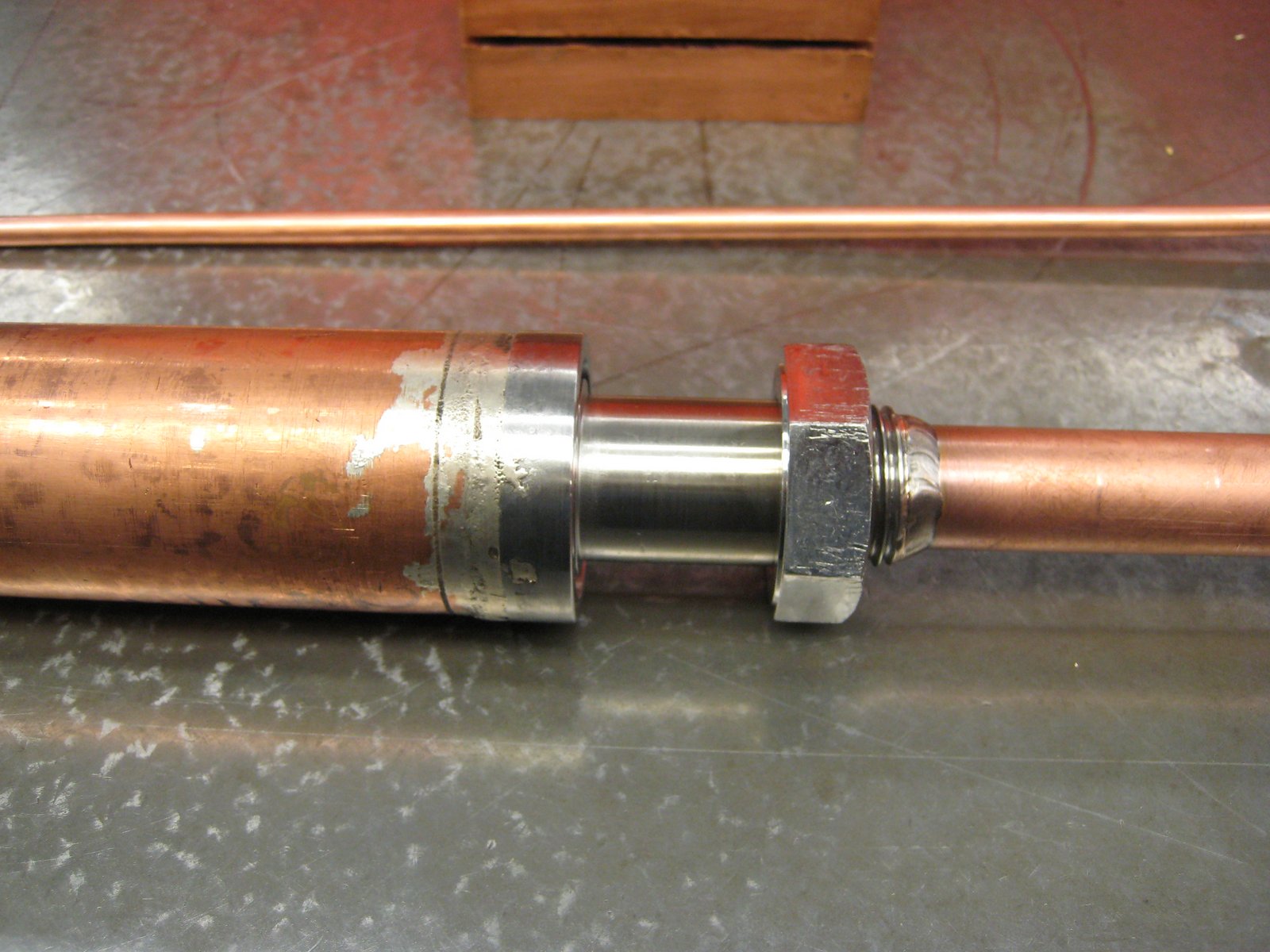
On the night shift Charlie found himself assigned way off in a corner of the shop to the gear department where he worked almost alone. This was something new for him. Never having had to make many gears this turned out to be a really great opportunity for him to learn another aspect of machine work. He ran gear hobbers and shapers making all kinds of gears to support the shipyard. He described some large worm gears and worms he had to make in that department for gun turrets of ships. The worm shaft that I thought was impressive was one made on a lathe using four steady rests simultaneously. He would cut the thread between all the steady rests then move the rests and finish the un-threaded portion where the steady had been running.  The first worm shaft he did like this was a forging of some steel alloy and would not cooperate and turn straight after removing the forging skin. They ended up replacing it with cold rolled bar stock to get the job done on time.
Puget Sound Machine Shop.

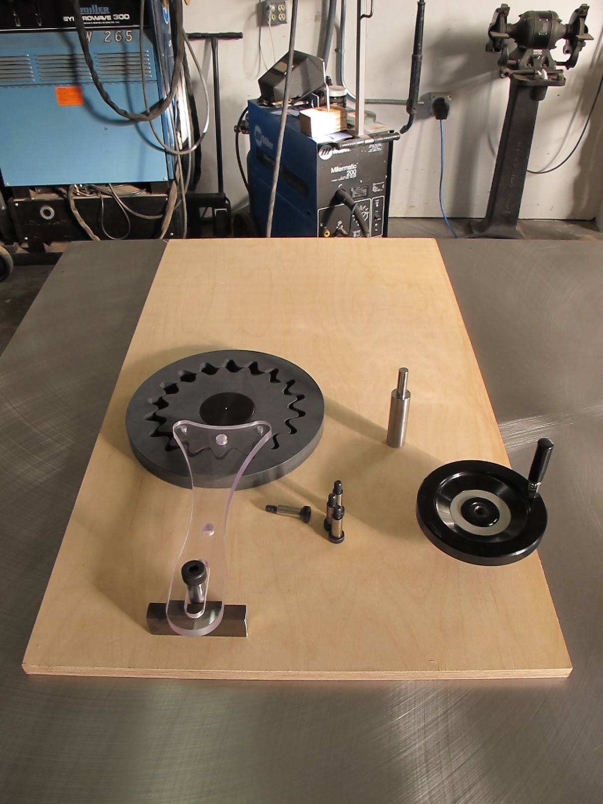
One of the other duties that the Swede assigned to Charlie was teaching a night class of young machinists. The yard was booming because of the war and they couldn't hire enough machinists and skilled men to handle the massive workload. A few nights a week they held an apprenticeship class in the machine shop to train new men. One of the projects they used to teach shaper operations were these little angled holdowns.

I'm not clear on what the time frame is at this point but the war in the pacific is raging and men, materials and equipment are heading out to sea in huge numbers. Bremerton was one of the places were battle damage repairs were sent and ammunition was streamed out to ships patrolling the pacific. One of the other things that was happening nearby the main naval base was a secret area where they were working on torpedo development. Charlie found out about it when the Swede asked him to make some very tight tolerance fine toothed gears that turned out were for some of the test torpedo's drive system. At this time torpedo's were less than perfect and submarine warfare was becoming very important.

Most of the gears he made at the Bremerton yard were on the smaller side. Another interconnected gear making story is a set of coarse pitch gears Charlie made at another company in the bay area years later that got rejected in inspection. He whipped out his gear tooth vernier and showed the inspector the numbers were correct for the tooth chord which is what the vernier can measure. The inspector corrected him because apparently there is a chordal correction that is used to compensate for large teeth on smaller pitch diameters. It is so small on fine pitch gears it can be ignored but on large teeth it makes a few thousandths difference to the pitch diameter. Fortunately the pitch diameter comes out big so its a simple matter to re-cut the gear a little deeper. Working in the Bremerton gear shop and making fine pitch gears for instruments and torpedo drives they just ignored this correction because it was smaller than their ability to measure.

I never heard how many students were in the machining class at Bremerton. From Charlies description there may have been ten or more students in the program at any one time. As part of their training they had to complete several projects to graduate the class. One project was the angled parallels where the students learned shaper operations and another project was one of those two way v blocks ones like the Starrett 567 block where they learned mill and grinding work. I see "student" versions of these v blocks at flea markets occasionally. They all seem to have the obligatory stamped name and class numbers hammered into them.
These are the only projects I recall from the story as it was related to me. All the students had to stamp their names on the projects. Most likely to keep people from turning in the same part ten times for a grade. The parallels I picked up out of the Gerstner had a name stamped on them. Charlie told me this was one of his students in the machinist class. I wish I could remember the name but I cant. So for this telling of the story I will just call him Robert Smith which is pretty close.

Charlie told me that Robert had a hard time with machine work. As Charlie described him he had little or no mechanical aptitude. The class was difficult for Robert but not for a lack of his trying. He worked hard but everybody including Robert knew he would never make a good machinist.

Around this time the Swede asked Charlie how many people in the class wouldn't make it as machinists. When Charlie asked why the answer shocked him. The Swede told him that the military was looking for men to send out to the front lines in the pacific and had asked around at the shop if they had any men that weren't suited for the trades they could let go. After hearing this he told the Swede that all the guys in the class would make fine machinists and he didn't want to give any of them up. This closed the subject temporarily.

After this Charlie worked extra hard with any students that were not up to snuff. In particular he spent lots of one on one time with Robert Smith to bring him up as quickly as possible. He did improve but it was still pretty plain to see that he would never be suited for any skilled mechanical work. I asked Charlie if there was anything this guy was good at in the shop but I guess they never found what that was.

It was just a matter of time before the recruiters came back through the shop. This time they went directly to Charlie and asked him if he had any men not passing the training class. He fibbed and said no to them again. Their reply was they would be back and if he didn't have any men for them they would pick some themselves. This put tremendous stress on Charlie. He knew why they wanted them. They were losing men by the thousands in the pacific islands so they had to come from somewhere to fill the ranks. Sixty years later he is telling me this story in his garage and I can see it still upsets him.

So after a short reprieve the recruiters, true to their word came back and demand they needed somebody. It was either you pick or we pick, the choice was Charlies. Even after working with Robert Smith intensely it was obvious that he would never make a good machinist. He was one of those guys that lacked whatever it is that makes a good tradesman. His gift was somewhere else. Charlie was frustrated because the man tried so hard and because of this it felt like some deficiency in his teaching abilities that was the cause of the problem. When I taught welding at a vocational school we saw a similar thing. There were guys that just lacked the hand eye coordination to become proficient weldors. No amount of practice seemed to make a difference. They either lacked some critical mechanic gene or we were really bad teachers. It seemed like there was at least one person on average in any class that really weren't suited to the trade.

So under intense pressure to make a decision he made the only honest one he could. Robert Smith would never make a machinist so he should go and try to find something that he was good at. This satisfied the recruiters and they left with their man. I guess Charlie had a chance to talk to Robert before he left where he explained the situation. Robert let him off easy saying he didn't know why he kept him around so long anyway. He blamed himself and his lack of ability for not being able to pick up machine work from such a dedicated teacher. They were able to part ways on a good note. Months later Charlie got a letter from Robert telling him that he was learning some new things and seemed to have found something that worked for him and his abilities. This was a huge relief to Charlie. I never got what it was that he found success at, it seemed vague in the story as he told me. So after this everything is back to normal and the training class graduated and a new crop of prospective machinists started on their new careers.

Quite some time later, months or maybe even years the Swede comes to find Charlie. The training class had ended and Charlie was back on day shift in the lathe department. The Swede comes up to him and tells him he has a couple of visitors at the office. Not used to having any visitors at work Charlie went up to the office to see who it was. As he approached he saw a well dressed man and woman waiting near the office. The Swede slinked off and left Charlie to make his own introductions. They introduced themselves as Robert Smiths parents.

After the introductions Charlie asked how Robert was keeping. They gently explained that Robert had been killed on some island in the pacific. He had volunteered to go ashore and do something and was killed in action and buried on the island with the other casualties. They went on to tell Charlie how much they appreciated how Charlie had helped Robert when he was struggling in the machinist class. Apparently Robert was a good letter writer and told his parents how Charlie had tried so hard to overcome his lack of mechanical aptitude. His parents had driven from somewhere out of Washington state to personally thank Charlie for all he had done for Robert when he was there. The kicker was they gave him a little package. When he opened it the parallels that Robert had made in class were in it. They said that Charlie should keep them as they had no use for them and Charlie might like them as a token of appreciation from them for helping their son.

Now I understood why he was so serious about these innocent parallels in his tool box. I cant imagine how he must have felt talking to the parents of this guy he played a part in sending to his death. Sixty years later the sting was still there for him. They didn't blame him at all, in fact they understood more completely than Charlie. These people had so much empathy they made a special trip to thank somebody that had shown kindness to their son.

In my experience it takes all types to make the world go around. Not everybody is cut out to be a machinist. Robert Smith may have been great at whatever he was doing that day on the island. This was an important lesson for me too. I was very lucky that I found out what it was I liked to do and was good at very early in life. I have worked with so many people that are miserable in their chosen work and hate every minute of it. I feel sorry for them since learning the simple secret of enjoying my work and staying true and honest to doing what brings me joy and satisfaction. The value of doing what it is you like to do and are suited for cannot be underestimated.    

Friday, October 26, 2012

Industrial notebook

At first glance writing about writing a notebook might seem to be a mundane boring subject. It is probably more boring than eating a good meal with a friend in your favorite restaurant, but very much less boring than watching paint dry or trying to remember something you should have written down. I'm sure most of the people reading this article have at least a collection of notes and sketches that are too good to throw away. Maybe your organizes and keep it all in a box or better yet a binder. If this sounds like you then read on.

In the late eighties I started keeping an industrial notebook. I think the habit started when I was taking some math classes at the local community college and got rid of the standard school loose leaf binder. Later on the idea was further driven home when I was involved with several patent applications and the need for documentation of the projects and inventions I was working on. For me my personal notebooks are a place with no rules, where I can jot down a thought or explore an idea or simply keep track of something I'm working on. Even today with the fantastic electronic devices available to us I still find a need for the paper notebook format. One of the engineers I work with and I frequently discuss the difficulty of capturing all the different types of information that come into our possession and how we can organize them and keep track of the valuable bits. My industrial notebook is one just one part of my personal information storage and retrieval system.
Why bother keeping a pen and pencil notebook in modern times? A few names come to mind, Henry ford, Leonardo da Vinci Hewlett and Packard and Michael Faraday to name a couple that few will doubt the value of their note keeping efforts. This article is by no means meant to imply that I'm even from the same planet as these guys, only to illustrate that people can learn something from history. So it looks like from history some really smart guys think writing stuff down is a good idea. My wife told me when I was writing my book that if you only write half a page a day, in a year you will have a good book.

We have quite a few electronic options available to us today, but I would argue that few have the simplicity, reliability and versatility of the lowly pen and paper. My version of the industrial notebook is just a simple continuum of thoughts and observations related to my current interests and projects that happens to end up on paper. The content of these notebooks cover every style of writing from notebook, logbook journal and diary to shopping lists for parts and materials. Officially each of these is a different type of note keeping with its own rules, format and content. I'm not much for the rules of the road with my note keeping. The things I put in notebooks are mainly for me, so whether someone else can follow what I'm up to is not as important as writing it down in the first place. Someone said, "The faintest pencil line is worth a thousand times more than the best memory." Sometimes all I'm doing in my notebooks is talking to myself by asking questions in sketches and by the act of recording the dialog to paper for possible future use.
I actually keep three types of notebooks because one system doesn't quite work for everything. The only difference in the notebooks are their size and location. Smallest of these is the wallet notebook. Second in size is the phone notebook. And the largest is the letter sized notebooks you see in the pictures. Of the three the wallet size is the only one I always have with me, at least if I have my pants on. The phone notebook is always on my desk near the phone and is used to jot down names and notes during phone conversations. Try writing an electronic sketch down on your cell phone while your talking on the same phone. I'm sure there is a way but I cant figure out how to do it as easily as I can with a pen and paper. For the large size book I have two running at any given time. One is supposed to be strictly for job related information, and the second is for my personal projects separate from my daytime job. Sometimes the lines get blurred and there is cross pollination between books but the main goal is to write ideas, thoughts and observations down somewhere to preserve them for future reflection and retrieval. The large notebook is the most important and valuable and the subject of this article. Inside the front cover I always put my contact information and the fact that I will pay a reward to get the book back.
In this picture is a small project related to motorcycles. I had forgotten about this little job until I cracked open the notebook to this page. I had a problem with the oil filler on one of my motorcycles that I created a special funnel for. The funnel had an adapter on it that screwed into the crankcase hole and let me put a bottle of oil into the funnel. I could leave it there until it drained fully without spilling any oil. The page on the right is a study of a set of blind spot mirrors that screwed into the ends of the handlebars for the same bike. Looking through these older books stimulates me and makes me want to head to the shop right now and built something. All this work was mostly forgotten until I opened the beaten up notebook to take a couple of pictures. The memories of the work flooded back reading the notes and looking at the sketches and pictures.
These entries are some photographs of a set of pyramid style sheetmetal rolls I designed and built back in 1996. I don't think anybody I knew saw the value of a digital camera back then. I had a computer but digital camera's were a bit of a rarity in the crowd I was in. Those were the days of film Fotomat and double prints please.
Another ancient entry. This was a small four inch rotary table project. It has the slightly unique feature that is reads angles in decimal degrees instead of degrees, minutes, and seconds. I remember thinking, my calculator gives me back decimal degrees why not make the rotary table decimal also and save the conversion. I still have this little table and use it fairly regularly.
Jumping forward in time. Here are some of the beginnings of the wabble drive featured in a separate article on this blog. The sketch on the left hand page has nothing to do with the drawings on the right hand side. This illustrates how the human mind jumps from one thing to another. These sketches were pasted into the main notebook from a loose leaf page so they are captured in one place or more. Most likely I didn't have the main notebook handy to doodle in so I wrote it down on whatever was at hand. If you follow a few general guidelines its pretty amazing how much you capture that might have been lost over the course of a project.
This photo shows a couple of cut sheets from a bearing catalog and some layout sketches. When working on a design its annoying to have to pull out the catalog or find the PDF again on the computer so I save the trouble and paste in the pertinent related pages so I have them in context with what I might use them for. These pages are design studies for the large etching press project. More on that as the blog develops.

Some advantages of the old school notebook method of information capture. Linearity of information is one of the most significant advantages of the notebook format. Notebooks by the nature of how you enter information show the progression and timeline of thoughts and the development of ideas. Drawings of any object can be made to fit in the pages of the notebook regardless of the scale of the item. In other words you can put a diagram of the solar system on one sheet or show the interaction of atomic nuclei, the choice of scale is automatic. A simple sketch with a mixture of text is easy in a notebook. Sketches saves pages of written descriptions and are my notebook language of choice.

Paper bound notebooks come in all manner of sizes from wallet, desk and letter. There is a size and style to fit all personality types and modes of carry. Notebooks are small, lightweight and requires no battery life or log on passwords. Archivally they can be excellent. Not as good as stone tablets but we can still read Leonardo's notebooks hundreds of years later as proof of the longevity of information storage. When is the last time you accessed data stored on an old floppy disc? Could you if you needed to? Have you ever had to have data retrieved from a hard drive after a malfunction? This is not to say that paper notebooks are fail proof. Your dog could actually eat one if they felt like it. Water and fire are bad for notebooks, but their also bad for computers and cell phones. I'll chalk that one up as a tie.

I rarely use an eraser in my notebook. If possible I use ink pen for as much writing of text, and as many drawings as I can. For complicated drawings I may use pencil to get the drawing looking right. One of my personal maxims is, Ink makes you think. I had a math tutor once that never carried a pencil, let alone an eraser. One day at the math lab I mentioned that it was pretty impressive that he used a pen only rolling equations off the end with hardly a thought. He told me something right then that has come true for me a thousand times since. He said he didn't use pen because of his mastery of mathematics and lack of errors, the reason was the exact opposite. If you use pen you cant really easily erase anything, so if you get stuck you can go back and see where you went wrong.  If you use pencil and erase your "mistakes" then you cant see the road you took to get where you are. And the worst thing is sometimes you are right when you think you are wrong. Committing ink to paper causes a small pause because of that pesky inability to erase. That small pause is actually you focusing your power of thought. He told me he had picked up the habit from a Physics instructor. At the beginning of the semester they all started a lab notebook. Their work output and quality were judged on the sole content of their lab notebooks. At the end of the semester if your lab notebook was only half filled with crud you got a half filled cruddy grade.

The act of writing ideas down causes me to think about what it is I am describing. That short pause as the pen or pencil touches the paper solidifies the though. I don't burden myself with a bunch of rules for putting something in the notebook they are more like suggestions. But I do have a few suggestions I try to be consistent with.

Notebook suggestions. Pages are never removed, date entries whenever possible, use as much pen as possible, never loan out your notebooks (like your toothbrush), review them regularly, no lower threshold on size or perceived importance of entries, never ever sweat spelling.

A few thoughts on reviewing what you write down. If its worth writing down its probably worth reading again.The chronological sequence of thoughts in a notebook once reviewed often leads to the next leap in the process. It also keeps you from barking up the same old trees again and again, or maybe finding that one tree you have been looking for.

People ask me how did I find time to write a entire book while I was working all the time. The answer is that I'm always writing a book of some sort. The harder part was organizing the useful bits so that somebody else would find it useful.

Further reading if you like the idea of keeping an old school notebook. Suggestions for keeping a lab notebook. My favorite type of notebooks. Try it for a year. Just a page here and there. Once you fill one and look through it again I think you will understand the allure and usefulness of the paper and pen notebook. So get cracking and start one today.


Wednesday, October 24, 2012

Bridgeport Spindle Speeder Video's

A few articles ago I described a special attachment for a standard milling machine that increased the spindle speed up to 25K RPM. I was missing one of the small cross section v-belts to make the unit run. The ordered belts came to the shop today so I put it all together and ran it for the first time in ten or twelve years. As promised there is some video footage at the end.
Attaching the pulley support to the end of the quill housing. It clamps to the housing with a single screw.
Ready to add the belts. In this picture I loaded up the little ER-8 collet setup. The kit has another tool holder that has a small sensitive hand feed drill chuck.
Belts installed and ready to shoot some video of the speeder in action. My tachometer only goes up to twelve thousand rpm so that is what you will see in the video's.
A nice short one of the speeder running at low speed.
A little longer one with some tachometer readings.
A run up of the speeder to twelve thousand rpm. Speed of the milling machine spindle is only at fourteen hundred rpm. A link to the original article.

Tuesday, October 23, 2012

TIG Welding Dissimilar materials

The title for this article is slightly misleading. A more accurate title is probably, a technique for joining copper to copper and copper to stainless to produce vacuum tight low electrical resistance weld joints with the TIG process. Over the past year we have tried this technique on a variety of non structural joint types and end uses with very good luck. The welding is performed at a much lower temperature than traditional copper to copper welding done with pure copper filler rod.

If you have had the need to weld copper together using an manual electric arc process then you may already be acquainted with some of the challenges. Because of the high thermal conductivity of copper, heating the material to welding temperature takes considerable welding current. At welding temperature the bulk of the part may also be very close to the same temperature because of this thermal high conductivity. At high temperature, exposed to air the the copper outside the protective shielding gas can form a tough scale that is hard to remove. It is also difficult for the operator to weld on a part that is glowing hot.
The job that started this experiment is an interesting one. The accelerator we installed last year required a low inductance grounding plane along the sixty foot length of the machine. The general idea is that all the grounding requirements along the machine are tied together in a single low inductance pathway to a good ground. There are a couple of ways the electrical engineers achieve this. One method is called star or multi point grounding. Star grounding is more difficult to install particularly if you are planning on adding more equipment requiring grounding later on. It involves running dedicated cables from each piece of equipment you need grounded to a ground rod driven literally into the ground. Our project opted for a sheet type ground plane under the entire length of the machine.

The material salesman was pretty happy when we placed the order for the copper sheet for the ground plane. When I got the specifications from the electrical engineer I asked him if he was sure he wanted to use 1/8 thick material. I told him the difference in price for thinner material to help him re-calculate how low of inductance he really needed. We ended up with 1/16 thick sheet. We call this a price benefit re-calibration.
We tested several methods for making the joints between the standard sheets. Copper sheet generally only comes as three foot wide sheets so we had quite a few seams to deal with. As a joint preparation we formed a material thickness joggle in the edge of the sheets that provided a parallel one inch overlap. On our first attempt with some test pieces bent with the same joggle we tried a solder paste combination. It consisted of particles of lead tin solder suspended in a gooey flux paste matrix. The idea was to butter the joints with this solder paste and then run a torch along the seam to flow the solder. It was quickly apparent in the test parts that the amount of heat needed was considerable. Added to that, the resulting joint was not very strong and failed the simple mechanical peel test. Bolting or riveting was not an option because we needed a low resistance joint the full eight foot width of the sheet. In the picture above the sheets are oriented with the eight foot dimension from left to right. Sixteen eight foot seams fully soldered or welded was starting to look like a real problem.

While we were testing the solder flux combination with mixed results one of the senior technicians Wayne casually walked by and mentioned he had joined some copper using silver bearing filler and the TIG welder years ago for something he built. Intrigued by this possibility I tried it on some of the test parts. The results were pretty amazing.

The filler material is a copper, silver, phosphorus alloy market under the trade names Sil-Phos or Silvaloy. More specifically the alloy we used was Silvaloy 15 which is 15% Silver, 80% Copper and 5% Phosphorus. The alloying of copper with silver and phosphorus lowers the melting temperature of the main alloy copper. Pure copper melts at 1984 degrees F and the Silvaloy 15 filler material melts at 1190 degrees F. You can see just from the melting temperatures that we can weld copper at a much lower temperature. I could see how this might happen by accident in the weld shop. Many of the TIG welding rods look similar because they are copper plated to keep them from oxidizing. If somebody accidentally used some of this brazing alloy to TIG weld then it would be pretty obvious that it could be used.

This was a huge improvement from the direction we were headed. We checked with the electrical engineer and they tested the resistance across the joint using a four wire measuring setup. With this type of resistance measurement the resistance of the alligator clips to connect to the part are removed from the resistance measurement so a true reading of the joint resistance is possible.

We tried a couple of setups to get the welder (me) comfortable. A couple of furniture dollies and a sheet of plywood became the makeshift welding gurney. Ahmet positioned the foot pedal of the TIG welder for me each time I scuttled to the next position along the seam. We were able to do all 125 feet of weld seam in a few days. The work endurance limitation was my neck position while laying on the cart. Not wanting to be permanently paralyzed I spread the welding out over a couple of days to save my tortilla chip like neck. The joints were welded with around 180-200 amps running a very fast travel speed. I was able to lay my arm on the copper not far from the weld zone without any discomfort. Directly under the copper ground plane was a concrete floor sealed with Rhino liner material. The liner was also unaffected by the heat from the copper welding. This seems to help validate the low temperature of the process.
Here is a picture of another little job where we used this same Sil-Phos filler material to join copper to stainless. This is a water cooled high current lead that passes through the wall of a vacuum chamber. The part in vacuum is on the left side of the picture. The copper pipe is welded to a stainless feedthrough that is mated with the heavy copper clamp. The original joint was silver brazed to connect to the copper to the stainless. The water path is in through the small tube connected to the tee fitting and hot water returns through the annulus between the small tube and the larger tube. Hot water exits through the other leg of the tee fitting.
 Here is a better closeup of the TIG welded joint between the stainless and copper. The joint on the left is silver brazed copper to stainless most likely done with a torch. You cant see it but there is an o-ring face seal to the left of the hex nut which seals to the chamber wall. We vacuum leak checked the assembly after welding to assure its leak tightness. We were able to get the background vacuum into the low negative nines with the leak detector pumping on it with no response from the detector. This is definitely not a ultra high vacuum part. The furnace this is installed in operates at a much higher pressure than we tested it to.
 Here is a shot of the test joint for the high current lead above. The upper copper section is a piece of the tube that was replaced in the repair. The cap screw was just a handy piece of stainless to test the weld.
 A test joint using Silvaloy 15 rod joining stainless steel to 101 copper sheet. I have not tested it yet but I'm confident this filler material will work well on steel to copper also. One thing we noticed on another copper to copper application is a color mismatch. If the weld buildup is removed by grinding and the joint allowed to sit and oxidize slightly, a color difference shows up between the filler metal and the copper base metal. The filler turns a dark grey and stands out from the base material. For some jobs this may be unacceptable.


Here is a shot of some special bus bar resistors we built recently. The requirement was they have a specific resistance within a fairly close limit. The tubing length was used to control the total resistance of the assembly. These resistors are water cooled and will carry up to 6.5 Kiloamps each.These were brite dipped after welding by the plating shop.
We tested the resistance across these joints using a four wire resistance measurement. They averaged around twenty Micro-ohms across the weld joint.Yes micro ohms not Milli-ohms. You cant take Micro ohm measurements with your Fluke multimeter. You need a special setup to get reliable measurements.
 I decided to do a sample weld in stainless steel to copper using the Silvaloy 15 filler. The stainless is a standard ISO Kwik flange half nipple welded to a 3/16 thick copper plate. No particular prep other than a quick buff of the copper with scotchbrite and wiped clean with alcohol. In this picture I put the hot part on a thick copper plate to cool it before I leak checked the welded assembly.
 After the sample cooled it went right on to the leak detector. I used the Kwik flange to make adapting to the detector easier.
 Less than a minute later the background is in the tens and ready for a spritz of helium. Our leak detector is a Inficon UL1000. This unit is super easy to use even for leak detection rookies like me. 
 Giving it a little helium around the weld filler metal. The flow rate of helium was pretty low, around five to ten bubbles a second in alcohol so I can see the bubbles. There was no response from the leak detector. It was probably my super human welding skills or possibly the process is pretty easy with this filler material. 

Some things I don't know yet about the process.

Mechanical strength of the filler material for structural applications. How it behaves in a joint of dissimilar materials mechanically with the base materials and filler dissolving in the weld. One of the other things that came to mind when I made up the weld sample shown above is how would it behave if I quenched it in water after the welding. Stainless by itself and copper by itself are unharmed by a water quench from welding temperature. I don't know how the composite joint using the silvaloy 15 would behave in that situation so I just let it air cool. It does seem like a viable process for making low resistance, vacuum tight joints in materials that have been traditionally hard to connect by TIG welding. Further testing is required to understand the mechanical properties of the filler metal in the as welded condition.

New data 12/12/12. We ran the test copper to stainless spool above through a test cycle that consisted of a UHV cleaning, bake out at 150C and then an RGA scan. Residual gas analyzer. The following charts show the outgassing materials that the scan picked up. We were only able to test up to 200 AMU (atomic mass units).
 The conclusion is this material is very suitable for UHV applications.

Friday, October 19, 2012

Wabble Drive Proof of Principle

About five years ago I built a small etching press for my wife. She has been interested in printmaking for quite a bit longer than that and had a nice press on her wish list. In a moment of weakness I agreed to build her a nice large etching press. This was shortly after looking at one in a studio and making the silly comment, "that looks pretty easy to build". After that she started her campaign to have me to build one to her specifications. As the pressure mounted I suggested that I built her a smaller press so she could get started with printmaking in her own studio. I could build it quickly compared to the larger press she really wanted so she could get something sooner. This had the added advantage that I would learn something from the small press build that would be scale up on the larger model.
The small press turned out good enough that she has been using it for the last five years doing a lot of printing of etchings and smaller monotypes. The need for a larger press is back in full force. Right now a much larger press is in the design department so she can finally scale up the printmaking operation. I decided early on that since I am probably never going to build another press this one should have all the embellishments and look like a piece of art in itself. It will become the center piece of her printmaking studio and a great example a home built press. During the design process I found I needed a gear reduction that had a large ratio in a rather flat package for the press. Typically these big presses have a reduction from the hand wheel to the roll of around fifteen to twenty five to one ratio. This is hard to do cleanly with chains and sprockets or with less than four or more gears.
This is a closeup of the gear reduction I figured out on the small press. I don't remember the exact ratio but its around six to one total reduction in two steps. The gear reduction is necessary because of the high loads during the printing process. As the axial length of the rolls increases the total pressure across the machine can be several thousand pounds. Fine control as the print enters the squeezing zone is one of the features of the high end presses like the American French Tool press. You can see these are massively built machines. Gigantic hand wheels are a signature feature of high end etching presses.
In this photo you can see part of the gear reduction mechanism behind the spoked handwheel. The handwheel input goes through a gear reduction and drives the lower fixed roll of the etching press. The top roll is movable to accommodate different items on the press plate and to vary the printing pressure. Basically a glorified laundry ringer, the inked etching plate gets squeezed between the two rolls and transfers the ink to the paper to produce an image.

Many different designs were scrapped before it settled on something I liked. The following is a description of a unique type of speed reducer sometimes called a wabble drive.

As the design work proceeds on the new large press I wanted to prove out the gear reducer as designed on the computer. This press will take advantage of accurate plasma and waterjet cutting to make many of the profiles used throughout the machine. One set of profiles in particular are in the gear reducer. The hope is that the reducer is insensitive to the tooth shape and will operate with laser or waterjet cut teeth without and finish machining. Also because it is just a little unique and interesting I decided to built a full scale model for testing.
This is the 2D study of the gear reducer I designed. It is officially and mathematically called a cycloidal drive. The slang or old time name is a wabble drive. It is quite simple and easy to construct and if it operates from net shape cut profiles it should be inexpensive. In this AutoCAD layout the input gear is the inner gear with the gear teeth facing outward and the reduced output is seen in the outer gear (teeth facing in). The long slotted arm is to keep the input gear from rotating in a circle. The input gear motion is restricted to an circular eccentric arc which moves the equivalent of one tooth space per revolution of the eccentric.

One of the main reasons we went in this direction is because of how compact this gear reducer is. It has a ratio of eighteen to one in a very flat package. I have never seen one on any piece of equipment which was another motivation for trying it out with a proof of principle. Anybody can put a bunch of chains and sprockets on to make a gearing reduction, but they lack the higher mechanical art that I am striving for in the large press.
 Here is a screen shot of the Solidworks model of the handwheel and gear reducer assembly. For scale the large handwheel is four feet in diameter. The plan is to fabricate the large handwheel from waterjet or laser cut sections in several thicknesses of steel to give it the old school cast wheel look. You can see the wabble reducer sitting at the heart of the wheel with the anti rotation arm pointing down.
Here are a couple of nice cast handwheels we spotted at the Alameda antique market. At four hundred bucks each they were out of my price range anyway so I guess I'll be building mine. In the old days they used the double curved arms on cast wheels to control casting shrinkage. As the molten iron cools it contracts causing some wheels to crack. Curved spokes have enough spring in them to prevent breakage.
For the wabble mock up scrounged PVC plate that was close to the thickness that the steel reducer will be the input and output gears. The shop CNC mill just had a major service and servo tune after we lost all the parameters mysteriously and wiped its memory somehow. The mill needed a test and some nice gentle plastic cutting was just the ticket. Later on we will do a ball bar test to verify the servo movements. Watch for an article on that event coming up in the near future.
The input gear anti rotation bar is a piece of polycarbonate rescued from the scrap bin. The extra holes are just fixturing holes where I bolted the material blank to the mill for profiling.
All the ingredients ready for final fitup and assembly. The center eccentric is the black Delrin bit in the center of the input gear. It gets an offset hole through it to mount the handwheel shaft. The eccentric offset gives almost a five eighths sweep of the input gear. There are always several teeth engaged with the output gear so there is no possibility of freewheeling.
 Indicating the eccentric boss in so I can bore the eccentric hole for the shaft. I always like three point contact when I hold a round puck like disc in the vise. It is way less prone to tipping than holding it in the normal vise jaws. The back v-block is a aluminum softjaw I cut for doing round parts in the mill. Normally it bolts in and replaces the rear fixed jaw of the vise. Here its just acting like a simple v-block.
This is just a set screw hole to lock the shaft to the eccentric. I wanted to show this picture because before I removed the bored eccentric from the v-block in the previous picture I used a pointed scribe in the chuck to scribe axis lines on the disc. It is a difficult thing to re-pick up two curved surfaces like this eccentric if you need to do something else after you lose the original orthographic reference.
Laying out the output gear retainers for the model. All they do in the model is keep the output gear rotating in the same spot. This is all built on Baltic Birch thirteen ply, plywood. Its the Mic 6 of woods with its super tight laminations and uniform thickness and  great flatness.
Couldn't wait for the real handwheel to give it a spin. The vise grips have copper pads brazed to the jaws so they wont mark the shaft in case you were wondering.


This is a short video I shot of the working model. Its fun to watch the inner gear wabble around. I can see how this type of drive got its nickname.

Thanks for looking. Stay tuned for more developments on the design of the large etching press.

Tuesday, October 16, 2012

Brushes Earplugs and Air hoses

Tomorrow I go for my twice a year hearing test. Into the booth to sit there straining to hear something I know is there but sounds like silence and the ringing of my tinnitus. I already know what the conclusion will be as the cheery nurse practitioner tells me, "Did you know you have significant hearing loss on your right side?"  This has been going on for quite a few years. I have chosen an occupation that carries some risk of long term noise exposure if your not careful. What happened to me is preventable for sure so I write about it to try to help a younger guy that is on a similar path. I guess I have finally made the big time since I'm hard of hearing like all the old crotchety metalworkers I learned from.

When I worked exclusively out in the shop I started wearing ear plugs early in my career. It took some getting used to but after the initial break in period even the sound of a MIG welder was painful to my unplugged ears and I couldn't work without them. My hearing problem started when I transitioned into the front office of all places.

An office is not what you would consider a high noise hazard area. In fact its downright quiet compared to the shop. I always thought the engineers that complained about the noise were big babies and they should try a few hours at the point of noise generation to get them calibrated to some real noise. When I moved into the office and started designing and doing more quiet engineer type work there was a subtle shift in the way I protected my hearing.

So in the old days you started the morning and put your ear plugs in and didn't take them out until lunch time. I was natural since you washed your hands for lunch and could use the same plugs afterward. When I moved into the office and was still keeping my hand in the shop work the all day system really didn't work. I might be out in the shop doing something on one of the machines when I would get a phone call or have to go to a meeting which meant I needed the ear plugs out. This pattern of interruptions is typical of a working foreman splitting time between the office and shop. Back and forth all day long between the shop and the office which have very different hearing protection needs.

What happened to me was that after a few thousand interruptions it became more practical to leave out the hearing protection. This is a self fulfilling cycle. As you begin to damage your hearing the need for hearing protection seems less acute. Louder noises become more tolerable. It is a slow process that is insidious and unrepairable. The shame is its really preventable. It happens so slowly I never noticed it until I had lost a good amount of range on one side.

Many years ago an old timer told me to never use an air hose on a machine. I listened and took his advice until I worked in my first job shop. Boy, a good air hose takes a fraction of the time to clean the machine or sweep under a bench than a silly paintbrush does. Job shops are about making money and moving fast so if you can clean your machine and be ready for the next job in a tenth the time then I think you know the answer. In a job shop machines are commodities which is the opposite of the toolroom or home shop where time and production is not the biggest factor. If you wear out your machine because you used it a lot including the abuse of blowing it off with an air nozzle but made the boss money in the process then you get a bigger newer faster machine with the same air nozzle and more work.

Air hoses at high pressure work better than air hoses at lower pressure. Simple physics. They also make a lot more noise. If you are wearing hearing protection the risk is fairly low even in a noisy environment and using blowguns. Unprotected you are almost guaranteed to be heading for a problem later in life. When we moved into our shop space my wife was very concerned about noise from air hoses and compressors since right next door to her studio is my machine shop and the main guy using it is already impaired. Her concerns are real.

I plan on a nice quiet compressor in the future so I can run some of my air tools but currently only have a little hobby compressor that's not really suitable for blowing off machines or running air tools. In the interim we have been enjoying the relative quiet in a shop sans compressor. I can even hear the radio while I work.

I improved my efforts at hearing protection by changing a few things around the shops I spend time in. It is important that they are still flexible enough for my work style and duties otherwise its easy to skip. The first thing was to go after the worst offenders, unregulated air hoses. We added regulators to all the air lines with dedicated blowers on the ends. After some testing the set pressure ended up around 35-40 psi to the blow gun. This makes a huge difference in the shop. It takes a little longer to clear off a machine when you have a lot of chips on it but the reduced sound level is worth it. Our scientific support shop doesn't do any production work so we really don't count seconds of cycle time in the jobs we do.
The second thing that has helped is buying multiple sets of comfortable high quality ear muffs. It took a few tries to find a set that fits me well enough to make me want to use them. I have found if I'm not more than a couple of steps away from a set I'll use them automatically. Sounds pretty simple right? This allows me the flexibility to switch between normal conversation and phone answering mode to machine operations without having to wash my hands to re-insert ear plugs. I have them on all the worst noise making machines in the shop like the belt sander and chop saw. In a small shop four or five pairs in strategic locations make it easy to do the right thing for your hearing.
Of course if its hot, or I will be wearing hearing protection for a long period of time the roll up foam ear plugs are still my favorite.
The second thing is I finally found a decent chip brush that holds up to machine shop abuse. For years I have tried all manner of paintbrushes and wisk brooms with generally poor results. My new favorite brush is made by the Gordon Brush Company  Lucky for me that McMaster sells their brushes individually otherwise I might have been reluctant to test these out of I had to buy a dozen on spec from the manufacturer.
These purpose designed tee slot brushes work great. The polypropylene bristles don't get permanently bent over and shorten the useful life of the brush. I don't care for the metal slot cleaner since I keep all my slots clean as a whistle. The metal slot cleaner just seems to get in the way when you use it while machining.
These high quality brushes have just the right amount of stiffness to dislodge the oily chips but still have a fairly light touch. Narrow enough to fit between the vise jaws when they are close together I can use them for many of the operations I would have normally just blasted with the air hose. Even with all these brush improvements there is still a need to blow things off with air or some other gas jet. I mentioned that I don't have a good compressor in my home shop just yet. The one I do have is basically a little machine that converts money in the form of electricity into pure noise with a meager output of air as a consolation prize. As part of a recent carburetor rebuilt I really wanted to blow some air through the small jet passages to clean them out. My wife was home so I was reluctant to fire up the compressor from hell and force her to wear earmuffs while I made noise. I remembered a can of compressed air I had like you would use to clean electronics with. As it turns out this worked better than the compressor could hope to. It had a nice small diameter straw with it that reached into the intimate recesses of the carburetor more easily than any air nozzle in the shop.
It is definitely more expensive than compressed air out of an electic compressor but it sure is quieter and more importantly didn't bother my wife. Being expensive makes me want to conserve it and only use it for things that really need a precision blast of gas. We switched to a new type of high volume blowgun. Acme Typhoon is the type and they work quite well. The air volume is impressive with a selection of available tube lengths. We tested the shortest and a twelve inch length and seem to have settled on the longer tube. The grip is cushioned and at a ergonomic angle.

So folks out there reading this do yourself a big favor. Learn from my mistakes and find a way to work a good hearing protection plan into your shop operations.