Friday, August 31, 2012

Helve Hammer Part 1

It was around 1999 when I took a trip out to visit my friend Wray Schlelin out in Massachusetts that I started forming the ideas for my Helve Power hammer. Wray had built a Helve hammer quite a few years before that to support his home based metalshaping business. He builds replacement sheetmetal parts for old Jaguar 120's and 150's. His customers are high end restoration shops and avid Jaguar club members that are rebuilding their rotted out barn finds. He supports his family from this work alone. I met Wray over the internet. I can't quite remember the situation but I think it all started with a article he did for Artmetal on the art related uses for the English wheel and some of his innovative tools and equipment.

Wray got part of his inspiration for a Helve hammer from a tiny little picture he found in a magazine or book. I'm pretty sure this is the picture below that got him started building his own helve hammer.
This is the helve hammer Wray built with only a tiny picture and some motivation. His hammer has been used regularly for something like twenty years or more. A testament to its construction. Its amazingly quiet. You can easily carry out a conversation standing next to the operator. Not much of a picture to go on but it was enough. Below is a video of Wray's hammer in action.
The origin of the Helve hammer goes back to ancient Chinese and Roman times. There are drawings of water powered trip hammers that are basically a Helve powered by a water wheel or bunch of young indentured apprentices. Helve means handle or shaft much like the handle on a normal hammer or an axe handle. They swing in an arc like the natural swing of a human but with a lot more endurance. This distinguishes Helves from other types of power hammers like Little Giants (below) and big Yoder type hammers which are both called guided way hammers.This means they can have both top and bottom dies that meet in a precision way to perform special work.
There are two distinct end uses that determine the construction and accessories for Helve type of power hammers. One is forging like you would see a blacksmith do where the metal is heated and worked red hot. The second type is the type I was interested in building which is for compound sheet metal shaping.The work material is much thinner and the material is worked cold.
Above is a picture of a monster Yoder hammer, probably from the aircraft industry. These are massive tools generally outside the hobby type user. I don't think you could run this in your garage at home and not have your neighbors coming out with pitchforks and torches to kill the monster. These are heavy duty industrial tools and are as scarce as moon rocks.
The simplicity of the helve hammer immediately appealed to me and my sense of design. Its just like hammering with a normal hammer but without the bursitis and sweat. I was interested in compound metalshaping but not all the heavy hand hammering physics lessons. This picture of a big Bradley forging helve is an example of a hot working helve hammer.

After seeing what was possible and being highly motivated after my trip back east I started my helve project in earnest.
An early design study. At this point I was thinking along the lines of a counterbalanced mass parallel action hammer. Not a true helve but similar.
This is a scan from one of my design notebooks. This is starting to show the final layout and some of the major design elements of the helve hammer. Note the curved arm on this study. My thinking on that was I might need additional clearance under the arm for deeply formed shapes. As it turned out I abandoned that idea when I looked at finding a chunk of quality hardwood big enough to cut that out of.

Another early design sketch. Here I was still contemplating an air cylinder as my power source. This is pretty close to the final layout. The major point here is that the construction method for the signature piece of a helve has been decided. At this point Its important to mention that I switched to a CAD system to do a more detailed layout and start the real mechanical design work.

Stay tuned for the next installment.

Thursday, August 30, 2012

Vaseline Fastball


True shop story. This unfolded right in front of my workbench around the time of the Challenger Shuttle disaster. I remember it well because the owner came through the shop and told each person.

This story takes place in a small sheet metal shop in the San Francisco Bay area. When I served my sheet metal apprenticeship I ended up working with an old crotchety New Zealander named Doug. As it turns out this master craftsman taught me many things and we became longtime friends. Doug had a sailboat that he built in in his backyard that almost stayed trapped there forever. But that's another story.  He moored the forty eight foot cutter not far from where we worked. In fact, it was close enough that we would sometimes have lunch aboard if the weather was nice. We sailed the bay almost every Sunday for quite a few years. Eventually he retired from that shop and sailed his boat back to New Zealand where he lives now.

This shop we worked in together had several departments. We worked together in the sheet metal department that was divided into small individual work spaces. These were separated on two sides with welding screens. I worked in the space next door to Doug. On the opposite side of me was another character named Steve. The way the screens were set up there was a space near the wall that you could slip through between the screen and the work bench. From my workbench I could easily see Doug’s bench and his little shop built toolbox. Right next to his toolbox Doug kept a small plastic jar of Vaseline sitting out and handy. All that sun and wind during our sailing outings on San Francisco Bay takes a toll on the skin and lips. Or maybe it was all the beer that scoured his lips that did them in, Anyway Doug almost always had chapped lips. He was a bit of a cheapskate and used the Vaseline to sooth his cracked peeling wind burned beer abused lips as well as lubricating o-rings. I would see him in the morning and after lunch putting some on his lips. Never thought much about it. Its just one of those weird things you notice and file away.

One day Steve came over and asks Doug if he can borrow the jar of Vaseline. Doug grumbled “fine” and Steve grabs the jar and off he goes. Doug never bothered to ask what he needed it for and Steve never volunteered. You have to know that Doug could be pretty gruff at times so you really did your business and got out of his sight as quickly as possible. Doug was one of those guys that if you were on his good side everything was fine. Problem was sometimes it was hard to tell which side was which. Lets just leave it at he had a bit of a temper and an o-too-thin patience factor. If he got riled up you did not want to be the cause of it.

When I worked with him almost everything I learned from him I learned by spying and observation. You never wanted to ask what might be a dumb question for fear of getting a blast of that spectacular temper. Not that he wouldn’t answer any questions, only that he had a very low tolerance for trivial time wasting blather. He had been forged in a merciless sweat shop in New Zealand where it was sink or swim. You never wanted to get chewed out or have his laser beam attention on you when he was in a mood.

Steve was a real nice guy and was one of the first guys to be friendly with me when I first came to work in the shop. This quickly deteriorated into outright competition between us. I advanced quickly in the shop and this didn't sit well with Steve who had been there for years. Have you ever known someone that never seems to make the right decision no matter what? Well Steve was one of those guys. Overall he was a friendly guy with some very solid skills.

In a close knit competitive shop like this one every little mistake is broadcast like a news bulletin. You have a better chance of hiding the fact you like to wear makeup and women’s underwear than keeping even the smallest screw up secret. Well lets just say old Stevie boy was on the front page of the f-up tribune more than his fair share.

So a little while later Steve slinks back into Doug's area and brings back the jar of Vaseline. He quickly returns it and goes back to work. The next day the same thing happens. He borrows the jar of Vaseline and disappears for a while then returns it quietly.  This goes on for the better part of the week. Finally one day when Steve came by to borrow the little jar of Vaseline. Doug, his curiosity aroused now asked him what he was using it for so often.

“Steve, what the heck are you doing with my Vaseline?”  Steve, obviously a little embarrassed a with a sheepish look on his face replied “Uh, I've been having a little problem". Doug cocks his head waiting to hear the reason his jar of lip lube was half empty. Steve squirms, obviously uncomfortable and blurts out, "My hemorrhoids have been killing me.” Now I don’t know about you but the image of Steve with his pants down around his ankles in one of the stalls with this jar of Vaseline doesn't bring anything good to my imagination.

At this point Doug’s jaw kind of goes slack at the realization why Steve has been dipping his finger in his personal chapped lip balm. Steve had worked long enough with Doug to know when the volcano was going to blow. He started backing out when Doug screamed at him. “You Bastard. Keep the f-ing thing”  Doug picks up the plastic jar with a look of pure disgust and hurls it at Steve as he scampers to get the hell out of range. The high velocity jar bounces off Steve’s back as his shoulder blades fold back in anticipation of the impact and hits the floor.

In about two minutes the whole shop has heard the story via the bad luck tribune.  Nobody  wanted to pick up the radioactive jar after hearing the story. I think the janitor scooped it up with his shovel finally.I would have thought that Steve might have grabbed it. Seems like he had a genuine need for soothing relief.

Wednesday, August 29, 2012

Studebaker meccanico

Knock knock. I open the shop door this evening and my nose is greeted with the smell of old car parts and grease. My neighbor Sam is holding part of the kingpin assembly of one of his ancient Studebakers up to my nose so I can look at it.. He explains the evenings challenge after I invite him in.
It seems pin number 14 in the diagram is not behaving itself and does not want to come out despite Sam's best efforts and biggest hammers. Looking it over it looks suspiciously like a tapered pin to me so direction might be important. Somebody has ground off the heads or whatever was sticking out flush with the forging number 11. So we cant tell which end is the small end so I don't have a clue which is the right direction. In the manual the pin looks to be tapered but its hard to tell in this old book. The insertion direction is not in the written instructions and the diagram only shows the pin on one side of the forging and may or may not be correct.
First attempt is just getting a good grip on it in a well mounted vise and trying to punch it in both directions. Under close examination you could not see the od of the pin on the one side because of the grinding job so determining which was the small end was not obvious. I figured that if I could move it even a little in either direction I would then be able to see the small end of the pin against the surface. So I started with the orientation shown in the diagram.This probably increases my odds a hair over fifty fifty but I'll take any advantage I can get.

OK. A few major whacks later and I'm wondering whats going on. Absolutely no movement and the hits feel like dead solid material. I like to use a bronze or copper hammer when I have to hit a pin punch or chisel with a heavy blow. The soft hammer grips the head of the punch and is less likely to slip off. Hard hammer on hard punch is a bad deal. Kind of like hitting to bars of soap together. If your alignment is not perfect then the hammer head can skate off the punch head and hit you, or worse the workpiece. How do I know that? Simple I saw somebody do it once......
After clobbering the pin for a while with heavier and heavier blows I finally managed to raise a little witness circle on the opposite side. The next odd thing was when I measured the circles on either side they were the same diameter. WTF? If the pin were tapered then one circle should be smaller than the other. Hummm. Well I wasn't making any headway trying the normal stuff like some heat, a little Kano Kroil and a good solid whack with a three pound hammer. When in doubt drill it out. After moving the pin a little I was able to spot the center of the pin accurately and drill a small hole through the center of the pin. Many times with stuck fasteners drilling a hole around a third of the stuck fasteners diameter through the center is enough to relax the offending fastener and removal goes easy at that point. This particular pin still wouldn't budge after drilling a relief hole through.
The irregular outline of this side of the pin got me to thinking that maybe the heads of the pins were mushroomed as part of the installation. This might explain why the pin refused to budge. I did manage to get a decent measurement of the pin from the hairline shadow I raised from the pin punching. Nominally the pin was 3/8 in diameter. I looked up taper pins just in case to see what standard taper pins have 3/8 on one end or the other. I found some that were close so I picked a drill that was a little smaller than the small end of the standard taper pin I found. Anything you can do to stack the deck a little in your favor is worth doing. The hard part is recognizing when you can stack the deck.
The mystery is finally solved. The pin is dead straight just like my measurements said and is .375 as best I can measure of the hamburgered remains. What is tapered, is a flat on the pin. This makes sense from a retention sense and as a way to eliminate any play in the assembly. But why didn't it show up on the end? There should have been a little flat that you could see from one end giving a person a clue what was going on. Sam looked through his parts books to see it they listed a pin as a replacement part.
While he was looking for the part in the book I was sneaking and making a couple of new ones from some cold rolled 3/8 rod I had lying around. Remember the rod bender article? So I get to mill a little flat on the pins at a small angle. I guessed at the angle since there were no references to go off and the mating surface was not tapered to match. Five degrees looked like too much by about double so I settled on three degrees. Actually a little less because I used a .250 pin under my little sine bar to set the angle.
This sine bar design is pretty nifty. I bought this off e-bay a few years ago and I really like it. It sits on the rails of a normal Kurt vise and is thin enough that it makes a variety of angle setups pretty easy. This monolithic sine bar was made entirely by wire EDM cutting. I checked it when I got it and Mr Ramos was a fine toolmaker. Its so simple and just the right size for Bridgeport size mill operations. I want to make another one without the vertical heel on it someday to add to the stable of sine bars in my box.
It took a couple of test fits to get the right amount of drive left sticking out for seating the pin. Sam reminded me he needed two pins one for each side of the car. Humm, I guess I'll be drilling another one of these out pretty soon.
So a couple of American made replacement parts for an American car. It was probably Korean steel so I don't get to claim a  hundred percent American made but I made somebody's day this evening.
Thanks for the fun job Sam. Bring something harder next time. Thanks for looking. By the way the diagram was right and now looks an awful lot like a flatted pin.

Tuesday, August 28, 2012

Close Tolerance Feedback Deux

Have you ever tricked yourself into believing something or a particular line of thought? Well this shaft end condition fail is turning out that way. But like all good problems your best learning often comes from these excursions from less than critical thinking. At least one good reason to never make a life changing decision without sleeping on it.

So my shaft problem woke me up early this morning without realizing it. Immediately it was on my mind and I wanted to get to it. I thought the alarm had gone off but half way through the drive in I looked at the clock on the dash and I was a solid fifteen minutes ahead of schedule. Now I know why traffic was so light. After the first cup of coffee I was ready to do some forensic investigating with my test indicator. First place I went was the lathe which was still set up from the day before.
 First I tested the end face with the rotation of the spindle. Part of me expected it to show something since the CMM had shown a problem with the end surfaces. I was surprised that the indicator showed that the end face as plopped into the machine were pretty good at just a few tenths. Hmmm, so I moved the test indicator to the OD of the part and tested it at the farthest point from the collet and right up next to the collet.

This is when I started to realize that I had probably out tricked myself about the cause of the bad end face parallelism. When It showed some runout (couple of grand) out at the end and near zero runout near the collet I started to come around to the idea that the shaft was just be bent. Duhh. This would pretty much explain everything I had seen and measured the day before. Nothing like a good nights sleep to clear out the cobwebs.
So a quick check on the surface plate with a test indicator and I pretty much solved my problem. I checked the shaft which showed the largest deviation from parallel on the ends.
  Holding the shaft from rotating I ran the indicator across the top of the shaft looking for the maximum number. I then repeated the check about every inch along the length. Guess what, the shaft was bent. I had convinced myself yesterday that this problem was caused by shaft whip in the headstock. It looks like that probably played no part in this mental exercise. So actually I'm pretty happy that I figured it out myself. But remember what I mentioned yesterday, Trust, but verify. Well now I'm off to precision inspection again to see if Bob's CMM agrees with my observation. How the heck do these scientists find something like a Higgs Boson? I cant imagine sifting through massive amounts of data and finding something that you cannot hold in your hand and interrogate. I guess that's why it takes them more than two days to sort it all out. The mechanical equivalent of finding the Higgs is like measuring the circumference of the earth with a six inch ruler and getting withing a handful of thousandths of an inch of the real number.
Bob ran the shaft for me again in the CMM. This time looking at straightness only. I learned something right away when I asked how he planned on supporting the shaft in the machine for a straightness measurement. Bob told me the shaft should be supported on its Airy Points  In short these are the support points on a horizontally oriented part that minimize droop or sag. I have heard of it before but never had the ability to detect errors this small or the need for this kind of support scheme for measuring.

What Bob measured was a series of slices of the round cross section of the shaft. From this he then created a three dimensional model of the shaft and found the best fit of all the axes of these cross sections. From this he can determine the smallest circular tolerance zone that these can fit on. In the case of the bad shaft it showed that the zone was .002 in diameter. Incidentally this is very close to the bends in the shaft I measured with the test indicator on the surface plate.
In this picture what we are looking at is the multiple cross sections taken off the shaft by the CMM. The line through all the circles is the best fit axis of all the cross sections, or the straightness. The cool part here is the little red bars that seem too corkscrew around the axis pointing away from it. What these tell us is the magnitude of the deviation from straight AND its orientation. That is very cool. So this shaft shows a general winding twist to the shaft as opposed to just a general bend in one plane like if you bent it over your knee.

This was a real fun mental exercise for me, and Bob actually had some fun also. I guess he never had to display the twist like that before so he got a little learning out of this seemingly simple little shaft. So in closing nothing is ever as simple as it seems and the devil is always in the details.

To err is human
To forgive is divine
To check is Engineering.

Thanks for looking.
.

Monday, August 27, 2012

Close Tolerance Feedback

Today I had an interesting feedback experience. Most people that have spent some time around machine shops have had to deal with inspection and measurement. For a large majority of normal job shop work the machinist with properly calibrated measuring tools can self inspect most of their own work. Where it can get tricky for the guys on the floor are situations where there are many interrelated geometric surfaces and relationships. Depending on the company or shop policy everything may get just routed through a large inspection department as part of the quality control or assurance program. The situation I ran into today was that the part that needed to be measured was outside the envelope of the better measuring tools at hand and to add to that I really wanted a definite known number for the overall length of the part.
From a previous post I mentioned a measuring gage I have been working on in my spare time. In the picture above you can see a length standard between the anvils of the coil pack measuring gage. This particular standard is one from our large micrometer set that I was testing out the repeatability of the new gage. Our coil pack happens to be an odd size compared to common micrometer measuring standards. I can easily order almost anything I want in one inch increments. For this job I decided to just create a set of calibration standards that were the nominal target dimensions of the coil pack. This odd number gets plugged into the electronic indicator and presto the gage is calibrated. I figured that I could get pretty close and the actual dimension didn't really matter as long as I know what the number is. A perfect opportunity to test my puny measuring skills against a gazillion dollar CMM.
So I went ahead and made two gages that corresponded to the nominal and horizontal and vertical measurements of the coil pack. I used some half inch diameter case hardened Thompson shaft we had in the material room and parted them off in the lathe a little long so I could precision finish the ends. The first step was to semi finish both ends to get an amount to remove to precision size. I left about .005 on the overall length for the final finishing. This was all done in a Hardinge tool room lathe in nice condition held in a 5C collet.

After finishing to length and measuring with some large digital calipers I was satisfied that I was pretty close. My guess at that point was I was within a grand (.001) of the target dimension. Now just to give you all the information these calibration rods are around a foot long and a half inch in diameter. A 5C collet has maybe an inch of gripping length for that half inch diameter. I was not spinning the part particularly fast maybe 800-1000 rpm.  Something I have noticed in CNC lathes with longer parts stuffed into the headstock is part whip and how it effects the different lathe operations. Part whip can show up at unexpected times related to gripping pressure and the resonant frequency of the unsupported part in the headstock. Most times its not a real big problem but occasionally the planets align and you see some of the negative effects manifested in your parts.

So I  trotted off to the inspection department to see how well I did with my lowly calipers and a light touch.
Bob runs the inspection department and was able to squeeze me in on the same day. I shot a little video of the measuring that is a little crappy, sorry. Note to self, don't use the zoom.
So according to Bob I did pretty well hitting the target dimension. Of the two gages I was within a tenth of the target on one and eight tenths on the other. The interesting part was the parallelism of the two faces. Since Bob's CMM is so cool and has all kinds of abilities he went ahead and checked the end faces for flatness and parallelism of the faces to each other. Flatness was fine on all faces and consistent around a ten thousandth of an inch across the half inch diameter. However the faces related to one another was off by .002 on one of the standards. WTF? That sure seems like a lot to me on such a small diameter. The length he measured was along the center line axis of the standard rod. So they are still usable if I relieve most of the larger diameter and leave the center alone where the length is good. This works out fine because what is normally called for on a rod like this is a slight curve on the end of the rod so that the calibrated length is the longest possible dimension that can be read.
So my conclusion is that the rod was whipping slightly when I faced the ends. By blind luck I clocked the two faces on the one that was off .002 so that whatever error was in each end was doubled by how I oriented the second face when I finished it.

How could I have done better? Well in hindsight I might have made a little plastic bushing to fit the ID of the headstock that supported the rod concentrically. Collet clamping pressure may have played a part here. I reset the pressure part way through facing the rods. This was because I didn't lock the tightening mechanism (lazy) on the collet closer which I of course bumped causing me to need to reset the pressure. Spindle speed could have been much slower and still produced a good finish. I'm hardly likely to calculate the critical speed for every part that sticks into the headstock. So who is to say I wouldn't land on another resonant frequency. I might have used a chuck instead of the collet because of its much longer gripping surface. Any chuck runout is not a problem because I was trying to make a surface perpendicular to the rotational axis. If the chuck did not grip the part parallel with the spindle axis I might produce a surface like Bob measured. Hmmm, something else to check on the Hardinge. Collet might be junk also. Half inch collets get used quite a bit. Another thing to check.

Hindsight is obviously pretty good so what could I have done to check it in the shop with normal tools and gages a machinist might have readily at hand? I think I would start with measuring it in the machine with a test indicator. In fact I think I will do it just to see what is visible rotating it by hand with a sensitive indicator on it just for my own satisfaction. There should be no whip with hand rotation and I would be comparing the runout of the OD in a couple of places with the end face. This might expose what Bob found on the CMM inspection.

So at first glance what looks like a no brainer part has all kinds of problems. Its always the easy ones that come back to bite you. Not very much error in the grand scheme of things but what if it had to be dead nuts? So the moral of this story is, Trust but verify.

I will post an update on what I discover when I measure the parts on the machine.

Sunday, August 26, 2012

Mary the Mannequin Part 3

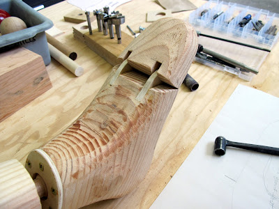
I'm kicking myself because I don't have many pictures of the construction of the head for the mannequin. It all started with a couple of chunks of four by twelve doug fir header lumber. By sheer luck alone I managed to glue them with the grain in the better of two orientations. Blind luck is truly 50/50. I only mention it because I'm mad at myself for not thinking about it when I was putting it together. When I glued up the two pieces I wanted to avoid any metal in the head because of the severe sculpting we had planned. I used wood biscuits and Titebond wood glue to connect the head halves together.

Have you ever seen the guys that carve wood sculptures with a chainsaw? There is a guy in Berkeley near Urban Ore and McBeath hardwood that does that kind of sculpting work but I never get to see him working. All I know is his friendly guard dog that is there over the weekends. I always slip him a biscuit through the fence if I happen to go by there. So I have always wanted to try one of those chainsaw blades that fit in a small grinder. This seemed like the perfect job for one of these blades.
Most of the shaping and carving on the mannequin was done with flap sanding discs and the chainsaw meat shredder disc. This is truly a material removal tool. I am reminded of some scene in the Soprano's or the movie Fargo whenever I use the thing.
It behaves itself surprisingly well for such an aggressive tool. Its sold by King Arthur tools and available online from Amazon or several other resellers. Be sure to check out the videos they have on their site to get an idea what these things can do. I found it really controllable partly because it runs so smoothly. You would think that something like this would be hard to balance at 15,000 rpm. I guess not.

So what happens when a machinist type does an art collaboration project? We I'll tell you,
 They use all the tools at their disposal that's what happens. Here I'm marking the feet for the toe articulation. I wanted the cut to be in the same place on both feet and perpendicular to the long axis of the foot. This was just the easiest way to mark them quickly. I need to fabricate a pencil holder that fits all my different height gages but I guess that will be another article.
This picture shows how I worked out where I wanted the pivot point for the toe section. I traced an elevation view of the foot and cut the template were we decided to make the pivot. The problem was the optimal place to put the actual pivot dowel. Its hard to see but there is a push pin simulating the pivot on the paper pattern.

In the shop you are always thinking about not running any body parts into your machinery. This project was a little creepy in that I had to bandsaw all kinds of anatomy during the building of the mannequin. The feeling was especially strong when I had to saw the toes off the foot. It kind of goes against everything you have been taught and learned the hard way about keeping body parts clear of machinery.
I managed to get past this queasiness and make the required surgical cuts. We had to add some material to form the hinge for the toes. Its just thin Baltic Birch plywood glued into the body of the foot and sanded to match the foot profile. The pivot is quarter inch diameter hardwood dowel.
I always say two heads are better than one. The head was the most difficult parts of the mannequin. It had to be proportioned correctly and have the right kind of neutral humanoid look without getting into fine detail like noses and ears. I did the initial scary roughing work with the chainsaw blade. The forensic evidence is on the floor in the background. My wife did the final serious artsy detail work. I got to a point with the chainsaw blade where I didn't want to go any further for fear of bozoing the head and having to glue up another one. Nothing like the threat of more work to make you be careful.
Ever feel like your head is in a vise? Well this is what it looks like. Here I'm getting ready to drill the hole for what is probably like cervical vertebra C1. This got one of the ball joints and clamp plates like the shoulders, ankles and wrists.
She's really starting to come to life here. Its weird when you are moving all the joints around and it just looks like an inanimate object and then suddenly it drops into a very scary human like pose. I'm sure this thing will scare the crap out of us for years to come. Incidentally the one tanning salon arm is a test for a staining color we will use for the whole thing at some point. 
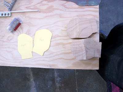
The hands were the next tricky spot. We bought some hickory at the hardwood lumber yard to make the hands after testing the soft Douglas Fir out. For anything with small detail this is the only way to go. It cuts like soft aluminum and holds detail in small cross sections. In this shot the palm blanks are roughed sawed out like a couple of mittens. We decided that the fingers would need to move also so I figured out a way to do that and attach them to the palms.
The pivots are made from brass wood screws that I soldered some copper discs to. A single slit with the bandsaw forms the slot the copper disc slips into. The pivot for the finger is a shorter brass wood screw counterbored into the finger. This mannequin has some pretty burly man hands.
Here I'm trying to explain to the patient just how the legbone is connected to the hip bone. Now everybody that comes over gets their picture taken with Mary and put up on a bulletin board in the shop. We call it paying the toll when we have guests. So make sure you take a shower and comb your hair and wear a nice shirt if you come over.

Hope you liked this series. We had some serious fun making Mary the Mannequin. The shop is coated in fine dust but it was worth it. We are thinking metal for the next one.

Precision Welding Ground Clamps

A year or so ago I was frustrated with the ground clamp on the TIG welding machine in our support shop at work. One of the problems was the new welding table we were using. We had moved the entire welding operation from the basement lab area and plunked it down in the middle of the machine shop. Part of the reason was to do the final vacuum seal weld for the induction cells for our project at work NDCX2. Having the welding machine upstairs turned out to be the best thing we could have done. The machine we used to do the magnet alignment was nearby and we could quickly button up the cells after measurement make room for more instead of doing the welding in batches. An added benefit was the adjacent machine shop always seems to need a weld here and there. In the machine shop we set up the new welding area around an old Taft Pierce cast iron surface plate. This is the beginning of my frustration with the ground clamp.

The Taft Pierce plate is heavily ribbed and has a thick rim that doesn't lend itself to a normal welding ground clamp opening. To solve this problem I attached a c-clamp type ground clamp to a large boss on the table and then attached the spring clamp to that. You might ask why I didn't just use the c-clamp ground clamp for everything?
 The reason not to use this type for everything is one they are big, bulky and a pain to use and move from one spot to another quickly and there were enough other jobs that the clamp type was just unsuitable. Can you tell I don't like this type? To finish off my frustration with the large spring type clamp I had something happen that in almost forty years of welding has never happened before.
I was welding one of the induction cells closed one day and had a spring type ground clamp like the one above clamped to one of the bolts that was protruding through the flange I was welding on.
The welding is performed with the cell horizontal as its shown in the picture above. These cells are roughly thirty four inches in diameter so you have to lean on the flange surface during the welding. Part way through this particular weld I heard the sound of the ground clamp coming off the bolt. I guess I had leaned on it enough to twist it off the bolt it was clipped to. Well when it came off it caught me under the arm and clamped onto the soft underbelly meat of my triceps. My arm was in the wrong place at the right time. If you have used these type of ground clamps then you know they have a pretty studly spring in them. It didn't hurt as much as you might imagine but it was significant.

The lower meat of the upper arm is kind of tender in particular the older you get. I took it off and didn't think much about it. My wife spotted the purple and yellow bruise it left the next day so I had some esplaininnin to do."Honest honey its just a welding hickey" Sounds lame right? To make matters worse she is a welder also and has never had anything so ridiculous happen to her. It would have been easier to explain third degree burns over half my body or a missing limb instead of a suspicious underarm hickey. 

Up to this is just the background of what I really wanted to talk about in this article which is experiments with alternate welding ground clamps. Part of the problem I perceived from my experience was that generally any particular welding machine has just one ground clamp even though it operates in a huge range of current levels and huge variety of jobs. The machine the arm pinching clamp was on is an older  Miller Syncrowave 350 and can run from 1 ampere (with the low current option) all the way up to 400 amps. In welding that's a pretty wide operation range.

When you get a new welding machine most folks look at the highest amperage the machine can produce and size the ground clamp to accommodate that highest current even when they know the machine will see that only a few times in its life for the average machine. I Asked myself the dumb question why don't we just have some quick change ground that we match to the job? What could I try on the cheap? If I went to a quick change setup I would need a quick disconnect to mount to the machine and a handful of the opposite side for the different clamps I envisioned. That would have taken too long and cost a couple hundred bucks just for an experiment. So I started poking around the bins in the old electrical cabinet. On the TIG machine I have at home the original owner really took the top end current ability to heart when they sized the ground. Its ground cable is something like 4/0 cable. It weighs a ton and to add insult they skimped on the length. Probably because the huge cable is so expensive per foot. On the same note a huge ground makes no sense when on the other end a lightweight 200 amp TIG torch is mounted.
My first cut was to make a sub ground cable. The idea was I could try it out quickly and learn something and see it the idea had any merit. I started with a scrounged copper alligator clip. I was surprised right away that a pretty modest copper alligator clip can carry a pretty respectable current. I selected the alligator clip based mainly on how large its jaws could open. This pretty modest clamp can handle a hundred amperes and costs less than ten bucks new. This idea was starting to look pretty promising.
Here is a shot of the completed sub ground. The idea is you clamp the humungous anaconda ground to the copper plate and then use the more delicate alligator clip on the more lightweight workpieces. It came in handy when I was joining a bunch of thin curved sheet metal parts that had to have the edges aligned precisely. The smaller and lighter clip didn't influence the alignment by dragging the parts toward the center of the earth.
In this picture you can see the sub ground in action. Some part configurations can be damaged from current flow back to ground because they may not sit on a grounded table well or only bear on some small points that are easily eroded under welding current. Clamping the ground directly to the part eliminates this kind of ground arcing damage.
You can see the scale in this picture. This particular alligator clip is rated for 75 amps. I liked the jaws on this one because they close together instead of with an offset like the 100 amp clip I used for the sub ground pictured above.
So the experiments continue. So far I really like the small lightweight cable and clamp. I connected them directly to a ground pad on the machine so I could have the option to switch to a heavyweight clamp if I needed without taking the machine apart each time.
The copper plate is sandwiched between the heavy cable and the machine lug. I figure I will just double up the grounds if I have any high current welding to do or just slip the end of the lightweight ground into and insulating tube to prevent accidental high current flowing through the small ground clamp.

Try it. I think you will like it as much as I do and its an easy afternoon project.

Thursday, August 23, 2012

Rod Bender

This was one of the easiest little tools I have ever made lately. Like a lot of the things I do there is a behind the scenes story to tell. This one starts maybe 30 years ago when I made a cheesy little bender for forming 1/4 inch diameter steel rod. The shop were I was working in used the steel rod as wiring looms to route bundles of wire inside high voltage switch gear. These wiring looms were kind of fun to build a little like road building for wires. When I first started making the looms I just bent the rod in my bench vise with a mallet and welded them to the interior of the switch enclosure. When I switched to copper jaws on my bench vise this rod bending operation just shredded the jaws for any other work. Right then I decided to build a dedicated rod bender. Don't laugh but I still have it. I'm pretty sure that is the original dowel pin in the center. I cannot ever remember breaking one.
Like I said don't laugh. I made it from junk I had lying around the method of all good scrounges. The frame is a chunk of angle iron that I bushed to hold a hardened dowel pin as the forming pin. The back fence is cold rolled steel that I milled the slots in using a drill press of all things. I have used the crap out of this bender making hundreds of bends in the quarter inch cold rolled loom rod.

It got borrowed all the time by the other guys that had to do looms in the equipment they were building. Well all things end eventually so when I left that shop Trayer Engineering my little rod bender went with me. Sure enough I started using it for other things since it worked so well on the rod. After a few years I had quite a little collection of bushings and blocks for doing all kinds of weird little forming jobs that came up.
So this little rod bender just moved around with me from shop to shop. We used it quite a bit at CVM and that's were the story gets  a little more interesting. It was only after I left the company and the little rod bender went with me that it gets funny. One of the guys from CVM came by my new shop for a  shop tour and social visit. We were walking around the shop shooting the breeze when he spotted the little bender and said, "Jeez you just about crippled us when you took your bender" I asked Marty why they didn't just build another one and quit whining about it. He then told me he had tried to get one of the other guys to draw it up for him without success. He even sweetened the pot with this guy trying to entice him by telling him he would build two of them one for him if he would just make a drawing for him. Well I'm part deaf but I know an invitation when I hear one. I kept my mouth shut and started thinking about it. The cool part was I already had it in mind to make a better one but it was a low priority because I already had one that worked.
 It always starts with a sketch around here. I have no business jumping on the computer until I can put something down on paper. It helps to stay in practice hand sketching. You never know when you might have to communicate with an alien species.
Part of the appeal of this bender is its simplicity. I didn't want to lose that in the new design. So I spent a few hours on Solidworks and made a nice little drawing package for Marty. I never told him I was working on it. I sent the drawings in a package through the mail with some other stuff  to him at the shop. Not wanting to miss a chance for a joke I labeled the outside of the box in big letters with "Erectile dysfunction home test kit" and addressed it to him. I'm sure there were a few laughs from the mailman over that.
A few weeks later I still haven't heard anything from him so I'm starting to wonder if he got the package. Finally he emails me with a question so I know he's working on them. True to his word Marty walks in one Saturday at the shop and he has the metal version of the new design bender in his hand. He did just like he said and build two of them at the same time.
They work great and behave like the original but smoother and tighter. The new bender has a much larger bearing surface on the pivot and the bending pin is removable so you can change pin sizes and add other types of dies (like tubing) to it easily. To make repeatable angle bends you just make a witness mark with a sharpie on the rotating part of the pivot. You could put a graduated scale but then you would have to remember the number. For each diameter of rod or tube the barrel will have a different position. So a witness mark in this case is less confusing. I suppose I could make an adjustable reference mark. Hmmm, might be a good upgrade. I also added a measuring scale along the front to make gaging the bend lengths easier. Its just one of those adhesive scales which happened to be numbered in the right to left direction. Where did I find that? I'll give you one guess, McMaster Carr.
The rod I just bent in the picture is 3/8 diameter steel. I haven't tried it yet, but I think this one will do up to 1/2 inch in steel. You can slip a tube or pipe over the spud on the right side for more leverage. So all in all it was a really fun project because of the collaboration. Marty had the time and willingness to do the machine work and I had fun designing it and seeing something useful come to life. Hope you will like it also.