Sunday, July 26, 2015

2015 Toolbox Giveaway Project

Loyal followers and viewers,

Its been a long time since I put up a written blog posting. For those of you that have been checking back once in a while thank you for hanging in there. Much of my effort goes into the Youtube channel work that I do and I only have so much free energy these days. For more current work you can follow me in the virtual world on Instagram and Facebook.

This particular post is related to YouTube activity as well. Some of you may know a fine gentleman named Keith Fenner. He has a YouTube channel that is responsible for getting me involved in making videos about metalworking, craftsmanship and the trades.

Every year now for the last three years Keith puts together a toolbox with the intent of finding a worthy apprentice/recipient to give it to. He calls this activity "What's in your box?" This has been hugely popular and directly supports young folks getting a foothold in the trades. Candidates or acquaintances of the candidate submit a video nomination for consideration. These candidates are voted on by some of the metalworking YouTube community and the box is awarded to the selected person.

Keith accepts donations during the year of tools and material to fill the boxes so there is an opportunity for lots of folks to participate and contribute to this great cause. A good portion of the tooling items he has put up himself. This it really a powerful demonstration of Keith's dedication to the trade and his willingness to teach and foster younger folks entering the craft. Check out Keith's website for more specific detail and rules for the toolbox giveaway.

As part of this years toolbox giveaway some of the YouTube machinists community have generously volunteered to actually make some handmade tools to contribute to this years TurnWright machine works toolbox giveaway. I think this is an incredible idea and allows many folks that support the trades and the toolbox giveaway idea to contribute something deeply personal like hand crafted tools.

Of course I volunteered to do a project as part of this years giveaway. I recently announced the fact on one of my weekly Meatloaf episodes . I let folks know that the project I intended to do was fully designed and ready for fabrication. I stopped short of actually telling what the project would be to the dismay of many viewers I'm sure.

My first problem was deciding what the project would be. There was no particular shortage of small projects offered up by the participants of this years event. The problem that I had was that most of the projects I have done at one point or another in my career. Sure I could do another one of these projects for the toolbox giveaway but I really wanted to do something unique that would be challenging and of high interest to the metalworking community. Also it needed to be small enough that any reasonably equipped shop could follow along and make their own with a little Yankee ingenuity. What follows is the description and plans for the 2015 toolbox giveaway project.

Who doesn't like a Wilton bullet machinist vise? I don't know too many folks that do not appreciate a high quality bench vise. Every shop should have at least one high quality bench vise in it. Until you have used one its hard to quantify the differences in performance and the sheer pleasure of using one.

Anybody that follows my work on YouTube, Instagram and now Facebook will know that I really love using and collecting tools. Bench vises are no different. I had the pleasure of using a good Wilton vise many years ago when I was learning the trades. Once you have gone Wilton you can never go back. Needless to say I have a minor collection in my shop. Here is a short history of the Wilton vise company written by kc-Steve over on the Garage Journal forum. The Wilton vise company is a real American success story.
Here is a shot of part of the harem of Wilton vises in my shop. There are actually a couple more but getting them all into a single picture would have involved some disassembly. 

This brings us to the subject of the actual project. We are going to fabricate a copy of the iconic Wilton Bullet vise from scratch. How the heck are we going to do that is the first thing that popped into many readers heads just now I'm sure. 

Just to be clear this is a welding fabrication and machining project. Unfortunately for all the iron casting fans out there we won't be doing any iron casting this week. One of my criteria for the build was that folks with modest home shops could follow along with the build. The blog article is a simple way to communicate the plans to folks that want to build their own. The actual build will be videotaped and posted on YouTube at the Oxtoolco YouTube channel. This video project series will accompany the blog article and document the techniques used and the entire build process.

Wilton vises were built in a huge variety of sizes and shapes. We will focus on the iconic "Bullet" vise design. This is the first and most successful configuration of Wilton vises ever made. Wilton offers a wide range of sizes. From the monstrous eight inch bullet vise with a twelve inch (300mm) jaw opening down to the smallest currently made bullet vise the three inch wide jaw bullet.

There is a particular model of Wilton bullet vise highly prized among Wilton vise aficionados. This particular vise was manufactured in the late fifties into the mid to late 1960's. Marketed to jewelry makers combined with another Wilton invention called the Power-arm. These tiny versions of the bullet design are fairly rare with vises in good condition selling for north of three hundred dollars at the writing of this article. 
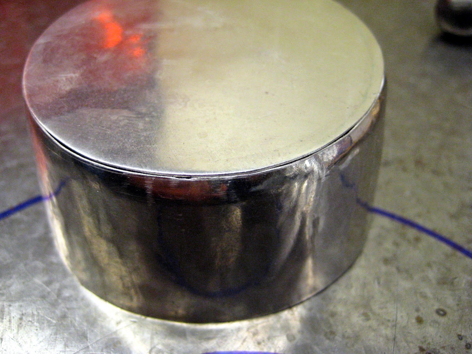
I know you guys are not surprised to find out that I have one of these in my collection. You can get a good sense of size and scale in this picture. The jaws of the baby bullet are two inches (50mm) wide. It can open its tiny little mouth to just at two and a half inches (64mm). Just what every toolmaker needs right?
Here is a baby bullet mounted on the omni directional Wilton power arm. This allows you to rotate and position the vise jaws at any angle for doing fine work ergonomically. This is also really handy for welding small parts as you can orient the part favorably for welding. 
Here is the corner on my welding table. I call this setup the NOGA vise after the multi directional indicator arms sold by the NOGA company. This vise can be re-positioned in a huge variety of positions allows access to weld even oddball joint orientations. This vise is a 2-1/2 wide with solid copper jaws. The copper grounding plate can just be seen peeking out the rear of the vise at the base.
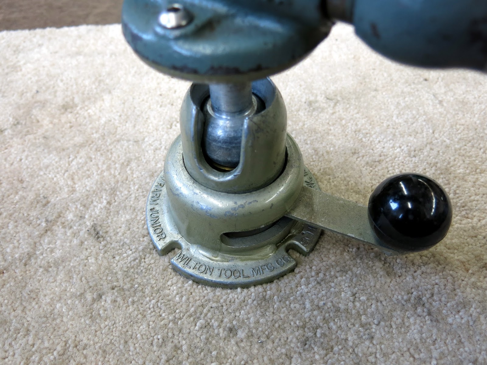
Close up of the power arm showing the pivoting ball arrangement. The ball is clamped by shifting the black knob. This pushes a threaded seat up against the ball locking it the desired position. The vise can rotate as well as lay over past ninety degrees as the ball stem goes into the slot. 

How the baby bullet project was conceived. Most projects in my shop start with what I call a chicken sketch. Named after the pattern that would be left if a chicken walked on the paper and left a design behind. Mentally I broke the vise down into all the different elements. Sometimes when a complex project is viewed as a whole it can be a little daunting. When you break it down like this into single parts each part magically becomes manageable.
The next step was to fully disassemble and measure all the baby bullet components. This took a little while to measure and model the vise up in Solidworks.  Measuring swoopy curved castings is not trivial with generally orthographic measuring tools. In this shot I have not added any blending radii to the vise jaws themselves. This is one of the tricky areas of the build. We want it to look like the original but since folks building their own may not have access to look at one first hand there will need to be some "Artistic License"allowed in this area.
Here I have added some radii to the vise jaws. It really changes the look of the model adding a few radii. You can go crazy modeling radii sometimes so I will probably leave it like this for the build. Some of the sharp corners will be naturally filled when the various parts are welded together. The video documentation will answer some of these questions for folks that are following along building their own baby bullet.
Here is a cross section shot showing the internal guts of the baby bullet project. I didn't model the threads on the clamping screw in case anybody was wondering. This is an accurate representation of the innards of a Wilton bullet vise regardless of its size.
All the materials for the project are readily available and common. I will list the McMaster part numbers for each of the pieces with the drawings so folks that want to follow along can easily source the needed bits and pieces.

Here is a link to a public dropbox file folder. You can download the PDF's of the parts of the baby bullet there. You do not need to sign up for dropbox unless you want to. It is a convenient way to get higher quality documents to the folks that want to build their own vise. Click on the link and select the file you want then at the upper right click on download. As feedback comes in during the build I will most likely add drawing revisions to the folder. These will be the normal drawing format of rev A, B, C etc. Hopefully I have captured most of what is needed to build the vise.

Baby Bullet Project PDF Drawing Link Click Here

I plan to build one of these vises complete on camera for the 2015 Keith Fenner toolbox giveaway. I have had a number of folks step forward and offer to volunteer their time and equipment to help with whatever project I finally decided on. Depending on the resources of the volunteers there may be an opportunity for many folks to participate in this really honorable cause and project.

I hope you follow along with the project and build your own vise for the pure fun of it. Please comment and test all the links for me.

Thanks for looking.

Tom Lipton


Friday, April 11, 2014

Expensive espresso cup

Well this is my first blog article in quite some time. I apologize for the long interval between posts. Lately I have been focusing on my Oxtoolco YouTube channel during the last few months building it up into a pretty good spot. So far so good. its taken off and surprised the heck out of me. If you like metalworking, tools and things mechanical then check it out.

This week I got to do a really fun job at work. Fun at work for me is a relative thing. Whatever it is it needs to be challenging and new and hopefully a little bit weird. The repair job I did for a materials researcher fits the bill to a teacup.
This is what I started with. Some sheet metal bits and a two different filler wires. What were looking at is a fairly large Platinum crucible. The body is drawn from a single piece of platinum and ended up approx .030 (.75mm) thick. The circular disc that will make up the bottom is a little thicker at around a 1mm. The two coils of wire are the filler rod for welding the two together.  Our materials group has the ability to recycle the material and make it into whatever form we require. Sheet, plate, rod and wire. Huge presses and wire drawing stands are right at their fingertips for just this kind of work.
I started by plannishing (smoothing by hammering) the body to round it up and prepare it for trimming. I'm using a soft faced hammer to lightly tap the ring without stretching it. A metal hammer against the metal mandrel would stretch the material and cause warpage and thinning. All I want to do is make it nice and smooth and round for the next step fitting the bottom.

The back story on the crucible is that it had been used to melt and fuse special glass compounds for research into energy efficient windows. The compounds being melted are hot enough to cause hot shorting in the platinum and failure in the original joint. Our materials department rolled a special higher temp alloy to use for the bottom of the crucible in the hope it will work better for this hot glass melting application.
Here you can see some cracking in the edge where the old bottom failed. Some of this is from me plannishing the material on the mandrel. I will be trimming it back to the lower blue line to make a nice clean edge for the new joint.
After I got the body nice and round the ends need to be made parallel. The side on the surface plate I just used some sandpaper to get it flat around the rim. I scribed a line at the correct length using sharpie as my layout dye. The rim was trimmed with the shears you see in the right side of the image. The band I trimmed off was probably worth a few hundred dollars. Incidentally the material behaves like soft copper. Not super plastic like but definitely soft.
The next part was a little tricky. The disc was irregular and not very round even though it looks pretty good in the picture. It was only marginally bigger than it needed to be with a couple divits that needed to be avoided. I taped the copper pad onto the surface to give me a place to scribe and place the divider point. Marking the platinum disc with scribe marks and a center punch was not on the menu.
Here is the circle cut out and fitted to the body. You can see I curved the body slightly inward to meet the disc. Better to have the fit in this direction that outward at all. This allows me to fit the corner and take out the curve as I go along tacking the the body to the disc and get a perfect fitup all the way around. Perfect fitup is the key to most welding problems.
Fitted up and ready for some tacking and welding. Later on I will even out the circumference and straighten the walls of the cylinder.
All welded up. The welding went pretty well. I used plain old TIG welding and DC current straight polarity to weld it. I did use filler in the joint because I planned on removing the weld buildup so the crucible would have a nice flat bottom.Yes I collected the filings when I removed the weld. All the scraps will be remelted and rolled into some other part later on. Incidentally Platinum does not oxidize at any temperature. You could almost weld this stuff without the Argon shielding gas. Notice the weld penetration shows zero signs of oxidation from lack of shielding gas.
Here is a view inside the crucible showing the weld penetration.

Here is the completed job. I missed a trick and should have made a cup of coffee to take a few sips out of as a joke. I ended up burnishing the outside to smooth small ripples in the wall and take out some of the curve near the bottom I mentioned earlier. Total weight of the finished crucible is just short of 90 grams. At the current spot price of Platinum that is about $4000 in material in the cup alone. 

I sure had fun working on it. It filled the bill for a fun job. The guy who brought me the job said he has another job for me this time in Gold. They need some reaction vessel for some crazy thing. He asked me if I was interested in looking at the job. I'll give you three guesses what I said and the first two guesses don't count. Thanks for looking.

Tom Lipton

Friday, November 1, 2013

5C Spindexer Indexer

A few weeks ago I proposed a follow along project on my YouTube channel oxtools. A viewer suggested an interesting problem involving indexing. His problem was how to accurately index 127 divisions for making a special gear. This might sound trivial at first glance but it quickly becomes difficult with standard tools and indexing devices.

The basic problem is 127 divisions is a prime number. To use standard circular dividing techniques requires compound indexing to achieve 127 divisions. Very few readily available and affordable dividing heads are equipped to do compound indexing without some modification. So what to do? The need for 127 divisions crops its head up when changing the gearing on a manual lathe to switch between inch and metric threading. As it turns out a factor of 127 happens to be 25.4 Starting to sound familiar now?

So now its actually an interesting project which is why were talking about it here. What I proposed in a video is to modify a standard cheap 5C collet indexer in a simple way to handle the 127 problem and make quick work out of typical spacing operations in the average shop.
These 5C Spin indexers are readily available and cheap at around $50 plus shipping. Many folks already have one of these indexers for the very same reasons. The project involves making some additional parts that allow the indexer to quickly index common divisions much like the common but much more expensive super spacer.

These units can already index 360 divisions with the help of a one degree pin vernier. Our modifications will make it quicker and simpler for small numbers of divisions while allowing us to directly index odd numbers like 127 and fractional angular indexes such as 7 or 11. Its limitation will be the ability to create the needed index plates and fit the desired number of hole on it.

Here is an example of an index plate with several patterns of equally spaced holes in it. The outermost circle of small holes has 127 equally spaces holes in it of 1/8 inch (3.17mm) diameter with approximately the same amount between the holes. As you can see in the drawing the disc needed to contain all these holes is pretty large. So large in fact that the stock indexer will not sit on a milling machine table without elevating it with this disc mounted. The maximum diameter that the stock indexer will support without a riser is roughly 5.6 inches.
In this shot you can see the maximum sized disc that can be used on the standard spin indexer when it sits on the machine table. So how do we get the desired 127 holes in a disc that will fit on the indexer without raising it off the table?
This is how we do it. By changing the radius that some of the 127 holes are on we can now put additional circles of holes and reduce the diameter of the disc to something that fits. The trick is that the angular spacing between any adjacent holes is exactly 1/127 of 360 degrees. The radius of the circle that the index hole lies on makes no difference as long as it lies on a radial line from the center of rotation of 1/127 of 360.
Here we see the needed parts to convert the stock 5C spin indexer to a spindexer indexer. In this example we show the 127 hole plate which is a very special case. For most folks a couple of different plates with some common divisions 2, 4, 6, 8, 10, 12 etc will make the most sense. The example of 127 holes is just to illustrate a method for making higher number or difficult number index plates of a small diameter. Obviously some of the common divisions can be indexed using the original plate and pin. The additional index plate speeds repetitive indexes and eliminated any possible errors of reading the angular scale.

The tapered arm is the index detent pin for plates with rows of holes on a single radius. It acts as a flat spring and engages the hole in the index plate with a tapered pin. To do higher order indexes with multiple index hole radii  such as 127 holes it is necessary to use the half index block part number 16. This slotted block allows you to disengage the tapered pivoting arm and re-engage it in another set of index holes on a different radius. The half index block is accurately located on the spindle centerline to avoid any errors caused by angular shifting.

To create the index plates the array of holes is put it using ordinate positioning in X and Y instead of angular indexing. Following the established jig boring practice of locating circular patterns accurately with this method is well understood and documented in books such as "Holes Contours and Surfaces" by the Moore Special Tool company.

The ability of the average shop to position accurately in X and Y rectilinear coordinates is higher than the typical ability to discriminate small angles. A simple milling machine equipped with a digital readout can make short work of making any desired index plate.

What follows are the drawings of the parts needed to modify the stock indexer and make it a spindexer indexer. Builders are encouraged to modify the design to suit their available materials and abilities and desired levels of embellishment and artistic style.


Thanks for looking.

Tom Lipton

Sunday, October 13, 2013

Tiny Drilling

For all the time I've been in shops there has been a story floating around that gets repeated whenever somebody has to drill a tiny hole. The story changes depending on who tells it but basically has the same cast of characters. The story goes something like this.

An American company developed a new drill bit for drilling tiny holes. The story teller never has a specification on how small the drill other than its really small. Smaller than a hair is what I've heard told before. This amazing drill took years of development and the company, once again un-named other than its an American company, is rightfully proud of their achievement in toolmaking.

The second part of the story gets even fuzzier. I have heard it told that the un-named American company had a rival or partner Swiss or German company that somehow hears about the new tiny American drill achievement. They politely ask for a sample of the drill for testing on their application or machinery. The American company rightfully proud, quickly obliges and sends them a drill for evaluation.

Depending on who is telling the story the roles can be reversed. The story seems better if the Swiss or German company is showing off their achievement to the Yanks.

So after some interval of time passes a package arrives back at the drill manufacturers doorstep. They open the package and find the drill bit they sent out. They look it over and see nothing so they send it back again slightly confused. Another time interval passes and the package comes back again. No explanation, no note, just a package with the drill in it. This time they look at it closely. To their utter disbelief they look and see there is a hole drilled through the side of their tiny drill bit.

Recently I bought about thirty pounds of old magazines from a guy at the Alameda antiques fair. I found this article in a old Popular Mechanics from the 1950's. It has almost all the parts of the story except the competition between the Swiss or German toolmakers.


This is from the 1950's Imagine what we can do today. I work with a fellow that has tools as small  as .0004 inches in diameter. Yes, ten microns. You cant even touch the tool with anything without breaking it. It takes a 60,000 rpm spindle to make it do anything. All I know is I would like to see the machinery that tool is made on.

Enjoy.

Tom Lipton

Tuesday, September 17, 2013

Monarch Lathe Survey

I had the opportunity to survey an interesting lathe recently. I appeared on our local Craigslist with a couple of sub-optimal camera phone pictures. Since it was local I sent the guy an email note inquiring about it to see if I could get a look at it. The machine is a 1964 Monarch Model 71 engine lathe. The lathe has a twenty inch swing (500mm) and  is seventy eight inches (2000mm) between centers.This particular machine has a hydraulic tracer attachment along the back side of the bed.
The first thing I noticed was the tailstock. What caught my attention was how massive it was. On closer inspection it has some very cool features.
Starting on the left the quill has very nice graduations engraved into a groove milled into the surface. The diameter of the tailstock quill was like a huge slab of baloney and over four inches around. Surprisingly the internal taper was only a #3 Morse which looked oddly small for such a massively built tailstock. The second cool feature was its own independent oiling system. I even gave her a pump for old times sake. Looking lower below the oiler we see a really nice feature for large lathes. The curved arm headed downward is a hand crank pinion that engages the rack under the ways and allows you to crank the heavy tailstock into position.
In this photo we see a couple of neat things. The lever on top is to change gear ratios for the tailstock. It has three positions, High, Low and Neutral. The lever shifts perfectly even though nobody has moved it in at least fifteen years according to the owner. I must have shifted it a dozen times playing with it. The angled handwheel is much more ergonomic than the standard type at the end of the tailstock.
It doesn't show very well but the cap on the rear of the quill has a graduated dial that reads to .001 (25 Microns). It does not move in and out with the quill it only rotates with no through hole to the quill ID. The lock levers, yes two can just be seen below the handwheel.
Moving along the machine we see some of the apron and cross slide. She shows some signs of rough handling on the carriage. In this shot you can see the pipsqueak Morse taper hole in the tailstock quill.
Looking down from the top we see part of the tracer attachment and control feedback. This side of the machine must have been bumped with a forklift as the spinning handles on all the handwheels were broken. Thankfully the shafts were not bent. I was able to turn everything even with fifteen years of dirt and dust on it.
I always liked Monarchs dual feed lever setup. No funky shifting required and you can engage both at the same time if you dare. Nice large diameter wheel with fine straight serrations on the rims. In this shot you can also see the center bed support. It has dual chip pans and a center foot support that wraps around. The chip pans are heavy duty and looked to be massive cast bits.
Up near the headstock now. The ways look rusty but in reasonable shape. Unfortunate on the rust but not the end of the world. At least there were no gouges near the typically heavily used chuck area. I believe Monarchs had hardened ways on many of their machines. Cam-lock spindle nose. The though hole was pretty small which is typical of many American lathes.
Here is some of the controls at the headstock. You can see it had electric range shifting and could go from 20 to 2000 rpm. Speed was controlled with the small black knob at the lower left. There was a hole above that housed some kind of electrical gauge not sure what it displayed as there were speed and motor load indicators to the right.
The ball end lever directly below the motor load meter releases the quick change gearbox and it operated probably as good as it did when this machine left the factory in 1964. In fact all the headstock levers moved and detented perfectly. For me this is a mark of quality, smooth operation of all controls with positive detents and engagement. I think the forklift did its damage up here also. The control panel was pushed in a bit. With the exception of the gauge it looked easily repairable.

Another shot of the headstock control area. Here you can see the Monarch badge. Their fonts changed over the years. Looking at this font makes me think fifties or sixties.

Now for the scary part, the electrical enclosure. This machine had some advanced capabilities and features. The tracer is basically a servo system controlled by a template and follower. This requires some control logic in an age of relays and contactors.
In addition to the tracer this machine could deal with changes in surface speed. I would guess it translated the template diameter and controlled the spindle speed to keep a relatively constant cutting speed on the work piece. It is also equipped with some hydraulic system that uses electrically controlled valves to change speed ranges. And it has infinite variable speed control within the major ranges. For all that you need a big box of electrical equipment.

It was a pleasant surprise to see the electrical panel in great shape and pretty un-molested. Monarch in their infinite wisdom even put a copy of the electrical schematic on the inside of the cabinet door. Real class and professional engineering.

I sure had fun going over this machine. Its for sale in the San Francisco Bay area. The price is $.19/lb Yes that's right, nineteen cents a pound. This once proud example of American ingenuity can be had for basically scrap metal price.

The bones of the machine are there and look to be in good shape. It is most certainly not a project for the faint of heart. Just the machine retrieval will be a major expedition. But hey, without expeditions and people willing to go on them where would we be? Somebody with some guts and mechanical aptitude would find themselves with a lathe made by one of the finest American makers with several lifetimes more work in her.

Thanks for looking.

Tom Lipton


Monday, August 19, 2013

Drill Press Vise Wrap Up

I'm calling it done at this point. After cleaning and repairing the bonus Kurt vise I acquired with the Clausing drill press its ready for use. I built a special base and anti rotation arm to make quick work out of clamping the vise to the drill press table.
The vise base is a .50 thick phenolic plate. I had the material left over from another job and it made sense for this application. Its strong and durable and wont mark the table. It has the perfect amount of friction that allows the vise to move around but is not so slippery that the vise will move under heavy drilling. The vise mounts to the plate via a couple of Helicoiled tapped holes. The notch is for the steel anti-rotation arm. I just scribed around the base of the vise casting and band sawed the profile and notch to match. You can see my chicken sketching on the side of the flat bar arm.
I wanted the anti rotation arm to be one inch wide. All I had in stock was two inch wide material. Nothing is easy right? I band sawed the two inch lengthwise and then milled the edges. Something to note when you do this type of splitting of a rolled bar. The cut immediately opens up and the two pieces come out curved from the stress relieving cut. I have had this happen before so I allowed extra cleanup stock so I would finish one of the bars to one inch wide. The clamps are holding a strong back back bar to keep the narrow bar from vibrating while machining.
So in this shot we see the vise mounted to the base plate and the anti-rotation arm attached. I found a cheap swivel socket wrench at HF that seems to work as a decent replacement for the missing Kurt article.
My McMaster box arrived today so I was able to complete the anti-windmill arm clamp. I think we all have a horror story on the drill press that we could relate. Its nice to not have any roadblocks to doing the right thing with clamping on the drill press.
The clamp allows the arm to slide in and out and pivot when loosened. When the clamp lever is cinched down the vise is locked in place. It can be quickly and easily removed if you need the entire surface of the drill press table for a large part. The Kurt vise is pretty heavy so it makes for a solid drilling experience.

So my famous drill press story goes like this. I was making some special plastic starwheels for a bottle filling machine. These look like big sprockets with teeth the same shape as the bottle being filled. Their purpose is to time and guide the bottles into the filling machine. These particular wheels were made from PVC plastic plate. It takes two star wheels to make a set they are connected by a spacing hub and attached with flat head screws. I needed to countersink the mounting screws after drilling the holes in the plates. We used to make these in the pre-CNC days by carefully pasting a full scale drawing on the material and then band sawing the curves and arms of the star wheel. It took a few hours to do a nice job on these with the sawing, sanding and filing. The mounting holes were one of the last operations.

We did a lot of 316 stainless in that shop so my countersink was pretty hammered. I went and got a brand new countersink from the machinist tool crib to use on my nice new star wheels. I remember it well because it was 3/4 inch in diameter and sharp as a scalpel. I saved a trip on the way back by picking up a flat head screw from the bolt bins to gage the countersink diameter. The mill was being used so I decided to use the drill press in the welding shop to countersink the holes.

Here where it starts to get interesting. I remember saying to myself, "I'll just hold this down by hand to the table" See this is how it starts, one little dumb thing. The next thing I told myself was, "I don't need to set the depth stop, It takes so long to run the damn thing down so far" I chucked up the countersink and set the drill press speed fairly slow.

These things happen so fast it always surprises me. The millisecond the single lipped countersink touched the edge of the pilot hole it snagged and sucked my star wheel plate right off the table. I somehow managed to hold onto the plate but all that did was make the countersink actually drill through the plate. Instead of a countersink for a 1/4 flat head screw I now had a three quarter inch diameter round hole in its place. My butt tightening event was over in about 500 milliseconds.

Every time I need to countersink soft plastic from that point on I either have the part securely clamped, or the cutting tool is non powered. Fortunately for me PVC cements well so I was able to make a plug and glue it in and re-drill and countersink the hole and save the part. With that cement the countersinking lesson was permanently bonded to my hard drive.

Thanks for looking.

Tom Lipton