Thursday, August 23, 2012

MICE Coil Finishing touches

Mechanical and electrical work on the MICE coupling coil is nearing the end. We can definitely see the light at the end of the tunnel. You know when the shipping crate shows up you are close to the end. This particular coil will be shipped to Fermi Lab in Batavia Illinois. The crate is a special job with an internal suspension setup to give the coupling coil a nice soft ride across the country. My friends at Nefab built the crate to specifications in less than a week. That is some great service. We could barely buy the materials for what they charged for an assembled crate.
Today the two technicians working on the coil, Ahmet and Jim concentrated on the quench protection diodes. These diodes operate as protection for the eighty five kilometers of superconducting wire wound inside the coil. Diodes are kind of a weird gate or electrical check valve. In one direction they allow the passage of current freely with very low resistance. In the opposite direction they have a very high resistance to current flow. They shed this energy in the form of heat when current tries to go the hard direction. When a superconducting magnet quenches it jumps from a coil with near zero resistance to basically a giant heater coil. The circulating current needs to be dumped somewhere so we send it to the diodes. The other weird thing that happens is because of the sudden change in current there is a huge jump in voltage because of the inductance created in the conductor.
You can just see the diodes compressed in the clamp. All this has to be insulated because of the potential high voltage created by inductance. The insulation in this case is Kapton. Kapton can hold off roughly 1kv per thousandth of an inch thickness. So .010 thick Kapton should hold off a voltage of 10kv. These protection diodes are clamped with Bellville washers and preloaded to around 300 lbs per fastener.
In this shot you can see the main leads of the coupling coil. These are interesting because of the S bend in the support. As the magnet is cooled the leads shorten quite a bit, The straight part of the lead is free to slide in the G-10 blocks and deflect the S bend. If the magnet quenches the leads would warm up and get longer which would cause problems for the electrical connection. The entire coil gets cooled to 4.2 Kelvin which is the temperature of liquid helium. Incidentally there is currently a pretty serious world wide shortage of liquid helium. I guess there are too many balloons being filled....... Seriously though the subject of liquid helium is pretty interesting. Did you know the government created a giant stockpile of it back in the thirties?
One of the final tricky steps is to add some very small strain gages to the coil. During operation huge forces are generated in the magnetic field and put the magnet structure under large stresses. We monitor those stresses with these tiny strain gages. If you look closely in the picture you will see four little bumps on each gage. These are where the signal wires get soldered on. The wire is about like human hair and almost as tricky to handle. These particular gages are the floating reference gages that are used to compare to the gages bonded directly to the aluminum magnet casing. The two types of gages behave differently so we establish a calibration offset based on the two readings.
Some real teamwork going on here. How many people do you trust with a hot soldering iron between your legs? Jim and Ahmet are soldering the superconducting wire into the lead support loops. The insulation on this wire is a pesky tough material called Formvar and is a real bear to remove.You basically have to carefully scrape it with a very sharp tool without knicking the wire underneath. Easy right? We used to use a chemical method but the chemical was outlawed because it was so evil. Gee I wonder why? I know, because it worked!

Wednesday, August 22, 2012

Mary the Mannequin part 2

We started the mannequin project using mainly soft wood because we had a bunch of construction lumber around the shop. Ideally this would be all hardwood but then I would really want to plan it more because of the expense of and additional effort using hardwood. Sometimes its nice to have the freedom to not worry too much about the material cost and just try some things out to see where they lead. There was no way I wanted to do a 3D electronic model and build the mannequin to a rigid plan just to make sure we used some expensive wood efficiently. Part of what we were trying to capture is the simplicity and rough hewn look of the mannequin in the inspirational picture. For that you have to move fast and a little loose. Fine for the artist types but the engineering side of my brain always screams "wait a minute" when a project gets kicked into creative afterburner.
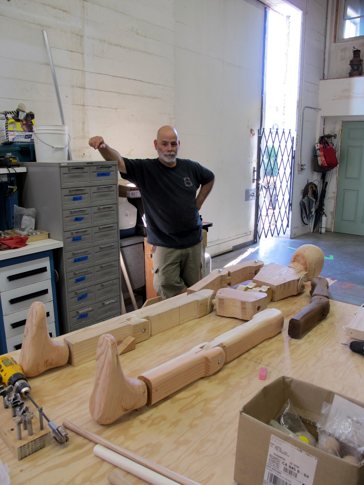
In this picture we have quite a few pieces roughed out and the mannequin form is taking shape. The torso in this picture was an early two piece version that we ended up junking because it just wasn't working. If we had made that in hardwood or metal we might have been much more reluctant to abandon it just because it looked a little off. In cheap construction softwood the decision was easy to toss it in the dustbin and make another..
She (Mary) has the new and improved torso Mark II in this picture. You can also see the lower spine double joint which connects the pelvis to the torso. This joint proved to be necessary to get the right amount of flexibility and articulation between the pelvis and torso. The tip angle of the pelvis proved important to posing the mannequin properly.  An early softwood rigid finger hand prototype shows up here also. 
The feet were also a critical item for us. At first cut we just band sawed  them out as monolithic feet  from 4 x 12 header lumber without any toes or any articulation other than the ankle. My wife spent a bunch of dusty hours sculpting the feet with a four inch sander with a 40 grit flap disc on it to get the right look.
Here is shot of the feet taking shape. Just looking at the picture you can see the difference in "presence" from the sanding and sculpting work. Holding some of these parts got a little challenging vises weren't designed to hold your foot in them.
It makes my ankle hurt just looking at this picture. I'm drilling the hole for the ball joint that becomes the ankle of the mannequin. I used hardwood balls clamped in place with retainer plates to allow the ankle articulation. The hole is just a flat bottomed hole made with a Forstener bit. These drill nice clean holes, accurate and without chipping the wood out.
This ball joint design was used all over the mannequin. I just changed the basic size depending on what part of body they ended up on. The balls are hardwood (maple or ash) and are readily available at a hobby shop like Michael's. These particular balls came from the woodworking supply store Rockler. I held the balls in the vise of the mill by sandwiching them between two blocks of wood that had a hole slightly smaller than the ball. Its important to drill the stem hole on center reasonably well. I glued the hardwood dowel stem into the balls with Titebond wood glue.
The next big challenge was the head which you get a sneak preview of in the picture above. Arguably the most important part of this project or at least as important as your head is to you. In this last shot the front part of the foot has been mobilized a bit. The lower leg didn't look right until the front part of the foot could move a little so the toes can sit flatter on the floor. You can also see the ankle ball joints here with their thin plywood clamp rings. Work of caution, pre-drill all your screw holes when you have a lot of work invested in a part. These were close enough to the edge to make me real nervous after the grinding work my wife put into these feet. If I bozoed the simple screwing job I would have felt pretty bad.

Stay tuned for part three.

Tuesday, August 21, 2012

Mary the Mannequin Part 1

This project started innocently enough. My wife cut out a magazine picture a few months ago of an intriguing nineteenth century artists mannequin. At first glance it looks crude and lacking in detail. But after you look at the picture more closely the uniqueness starts to come out and grow on you. Whoever the long dead craftsman was they were able to capture the essence of the human form with some very crude shapes. The more we looked at the picture the more we knew we had to build something. The antique dealer Hawker Antiques thought it was interesting enough to ask a pretty special price.
First a little back story. As the shop started coming together I managed to score an old Doall vertical band saw. A neat lumber recyclers in Petaluma Heritage Salvage wanted to sell it to make room for a shop expansion. You guessed it found it on Craigslist.
 This piece of equipment was the beginning of our mannequin project. These are great folks doing a noble thing and managing to make a decent living in collecting and re purposing wood that a few years ago might have been burned to get rid of. I got an awesome more than fair price.
The saw is an older Doall V-26. It weighs over 2000 lbs and is about eight feet tall. As the name says it has a twenty six inch throat.
It needed a couple of new variable speed belts and some general cleaning to put into service. They don't build them this heavily anymore. This has a massive welded frame and base and a huge webbed cast table. Heck the guards are made out of one eighth in thick sheet metal. Doall wasn't messing around when they built these. I'm thinking about how I'm going to get it off the pallet jack without killing myself.
This is how it starts. A few study sketches to get a general direction going and off you go. I decided to prototype one of the joints using simple cuts with the new band saw.Normally were not what you would consider wood people. All our training and careers have been spent with metal fabrication. Part of the reason for using wood is we felt it was part of the feeling of the original. That patina of old wood is wonderful. Wood also allowed us to make the project more three dimensional without increasing the work much. We were trying for a quick simple execution to try to capture the simplicity without any super fussiness about anatomical accuracy or life likeness.
A few cuts later and we really start to get excited by the possibilities. The scale was determined by carefully measuring my wife unit.

Stay tuned for part 2  Goodnight for now.

Monday, August 20, 2012

Sunday afternoon repair job

My neighbor the antique dealer brought over one of his typical jobs this weekend. It usually involves some metal bit that has seen some kind of mechanical injustice and or application of brute force.Its a wonder how these things manage to make it to the future in such good shape. Its a testament to the people that designed and built some of these things.
This repair involved a cleverly designed sheet metal bracket that allows the legs of a antique Foosball table to be easily removable for shipping. Fortunately for me there was a second bracket mating bracket that was in reasonable shape so I could see what had to happen. The bracket is steel, and about 1mm thick. It is a deep drawn and pierced shape which is interesting all by itself. I would be interested to see the die that produced this particular piece. It always amazes me the work behind the scenes to get a product to market. This table might be fifty or more years old. Some old guy designed a drawing die that some long dead draftsman faithfully drew up to his instructions which then went out to the machine shop to be built. All this for one little hidden bracket of many similar parts on this obscure leisure game.

If you are interested in this work there is much to be learned from the folks that have gone before us. I always tell my students to be curious and study existing common items. One of the most fascinating things I ever did was to take a run of the mill household washer and dryer apart and study the parts in detail. That experience is for another post but it was highly educational and eye opening from the mechanical design perspective.
So the little trashed bracket in the first picture is supposed to mate with this nifty rotary locking device. When the cross brace is installed a flat blade screwdriver rotates a tapered scroll that pulls the assembly together into a tight wiggle free joint. Its worth studying here because in practice easily assembly and tight fits don't always work out with easy to manufacture loose tolerance parts. The competing needs of cost, tolerances, and simplicity make a joint like this a little design challenge.
Here you see the one good bracket installed into the rotary locking device and snugged up. Another subtle design point is the little barbs you see at the top of the picture which help to lock the bracket into the wood. These are part of the die work that some engineer thought of way back when and included in the stamping. If your going to make a production tool to make something like this in quantity then by all means get all the features you want included right from the start.The initial die cost is higher but it pays you back with every part that comes off the tool.
Using smooth jawed pliers and some careful hammer and punch work I was able to straighten the damaged bracket. It became apparent that the one I initially thought was good turned out to be missing a small bit of material in a pretty important area. Between the two brackets I was able to see all the features of a perfect bracket.
Fortunately for me the material was steel so I carefully TIG welded the cracks and added some missing material to complete the job.So a fun  little repair job and a happy neighbor. I probably raised the value of the this Foosball table thirty percent just by a simple repair.

Too many things get thrown out for the want of a simple repair. In this case it was an "antique" with some perceived value just because time has taken it out of context. I submit that we throw away too many items that could be easily fixed but we are just to lazy to lift the hood and have a look.Move them forward in time fifty years and now they are cool old vintage items that people pay three times what they cost new just to put them in a curio cabinet.

Doing my part to repair and recycle I  have rescued several very nice space heaters from the scrap metal hoppers. This particular model has a built in tilt switch that in the event the heater tips over it cuts the current so it wont inadvertently start a fire. When they do get kicked or tipped over the little safety switch does its job and breaks the electrical circuit. Depending how hard it got knocked over can mean the switch gets stuck in the open position. Kind of a fail safe type design. Incidentally trying to design something to fail in a particular and very specific way is a pretty tough job.

I was curious why so many of these nice heaters were ending up in the dumpsters. Curious Tom opened one up that didn't pass the onoff test to see what was going on. Low and behold the little safety switch was jammed in the open position. A little tweak with a screwdriver and wham-mo it works again.

Moral of the story is, be curious and lift the skirts and open the hoods of your mechanical contraptions. You might get a pleasant surprise.

Wednesday, August 15, 2012

Spent the Day in the Machine shop

Finally I got to spend a little time in the machine shop today. Last couple of weeks have been pretty busy with work in other areas. A few months ago during the assembly of one of our large superconducting dipole magnets I noticed a couple of the technicians had to take some rather awkward measurements. They were trying to use some old vernier calipers and some loose parallels to take a precision measurement. They were using these ancient old calipers because they had the longest jaws of any of the tools available to them. Imagine a large square block around fourteen inches square and you need to measure somewhere near the midpoint of the square. You need a deep throat measuring tool to reach to the middle. Micrometers in this size range have a pretty decent throat but the shape of the frame limits how far you can reach. There was a genuine need for a specialized gage to reach the center. In my spare time, whatever that means, I managed to put a little design work toward a custom deep throat coil pack measuring gage. The main shop waterjet cut the frame profiles for me saving quite a bit of machine work. A few parts piggybacked on a several McMaster Carr orders and I was ready to make something. All I needed was a little time. The hardest part.
I didn't take any pictures of the early blank parts but you will get the general idea. The aluminum profiles were waterjet cut out of 1.5 inch thick aluminum plate. The silver bar at the top of the picture is hollow Thompson linear bearing shaft. I like to use this for shafting I don't need to modify much. It has a nice hard surface and is smooth for sliding fits. This allows items like the aluminum beams of the gage you see here to move easily when you need to make large size adjustments. On the right the weird shaped profile you see is where the dial indicator will be mounted. The odd profile is just meant to protect the electronic indicator from getting smashed or bumped. Waterjetting the profiles is a cheap way to add simple functionality for not a lot of extra work. If you had to machine all that then it wouldn't even be there. Bottom line is the waterjet is a great value added tool and technique. Like all things you need to understand its limitations. Read a little more about Waterjets here.
Above the indicator housing there is a simple parallel flexure device. I added this so the gage could be quickly and easily calibrated using a length standard between the gage tips. Instead of trying to position the bars super accurately in tiny increments sliding on the Thompson shaft, you just dial a set screw to move the indicator in relation to the standard to calibrate the reference point. The flexure membranes are made out of .063 thick blue tempered steel shim stock and waterjet cut right to net shape and size, no machining. Everything you see so far came from McMaster Carr. The indicator, the flexure material, the Thompson shaft and the gage tips which you will see later. My motto is, "If you cant find what you need in McMaster Carr then you need to re-design"
 In this shot I have the indicator housing and flexure assembly in the vise to see what kind of adjustment resolution I have for the calibration. The screw is hidden behind the flexure where you see the Allen wrench going in to prevent unwanted twiddling after calibration. The test indicator shows me how the adjuster tracks and repeats. I had some worry that it might not be stable enough but it looks pretty good after trying it out. The flexure is pretty stiff with the short membranes.

To be continued.

Sunday, August 12, 2012

Harsh Easel Project part 3

When it comes to paint I usually skip it on my own personal projects. I think its because I want to start using the machine or device right away and the time it takes to prep, paint and wait is just not worth the bother. It always seems to cost more than I'm willing to pay which adds to my list of reasons to go naked with most of the things that stay in my shop. For customers that's different. Paint gives it the "yes I'm finished" look and as a visual value added is pretty powerful. Needless to say Bills easel was getting painted. The conundrum was what color? Keep in mind this is an fine arts oil painter well versed in color theory. Cruising through the aisles at Home Depot I found some hammer tone silver that looked pretty good on the can. I bought some and tried it out on a scrap piece to see how it went down and how it looked after it dried. Results looked good and my wife gave her artist input approval. If I decide to paint something for myself the default paint I use is Steel It This is a polyurethane coating with stainless steel metal in the paint itself. I leaned about it many years ago when we rebuilt bleach filling machines. This stuff would go on plain steel and hold up to splattered bleach for years. Its a bit expensive, but the really good things usually are.
 Here is a closeup of some of the hammer tone paint. The dark bar in the middle is the guide rail and is hard anodized aluminum.
Paint was a problem for the expanding side frames. These telescoped inside the main frame on custom Delrin bushings. Since I couldn't have paint on these sliding parts I made the frames out of stainless square tubing and got them electropolished. The brass bar you see is an anti cocking guide for the extension frames.
Delivery day finally. Getting it out of the truck was the easy part. His studio was up on the second floor up a flight of rickety stairs. I totally forgot about getting it up the stairs until the day it was delivered. The whole thing weighs a couple hundred pounds and I wasn't in the mood to kill myself or do any tricky rigging job.
Whenever I have to go into the field on an installation or setup I always have my portable tool kit. We took the easel apart into some manageable chunks that Bill and me could schlep up to the second floor.
I think Bill is thinking what the heck have I asked for. How am I ever going to get this thing back out of here.
A few final adjustments and were almost ready for a test drive.The turnbuckle with the special knob is to adjust the vertical angle of the work surface. It has the ability to adjust both positive and negative angles. Something I learned was that artist sometimes want a negative angle depending on ambient light in the room or shadows cast on the work surface. I never would have caught that without Bills input into the design process.
In this shot you can see his old wood easel on the left.The new one is steel, stainless steel, Delrin, and aluminum. Why use one material when you can use them all.
A fun project with a good outcome. Bill was very happy and continues to use the easel at present. I made one repair a couple of years ago when the cable jumped out of the centering block I mentioned earlier. I added a cover plate and the easel seems to be holding up nicely.


Additional shots showing some of the other design features. The top picture shows the carriage lock mechanism. This has a right hand left hand screw assembly that clamps the frame to the  guide rail. The hinges are simple flexures made from spring stainless sheet. Another thing I learned about oil painters is they scrape the canvas pretty aggressively. Without a brake or lock of some sort the force from the scraping would have moved the thing up and down.For this same reason the casters on the easel lock both the rolling and the swivel action. This provides the most stable setup you can have with four swivel casters.

Friday, August 10, 2012

Harsh Easel project part 2

After playing around with the commercial counterbalances I started thinking about systems with long travel that use springs. One of the systems most of us have seen are garage door openers. The type I'm talking about are the hinge type with the big scary extension springs. These springs are manufactured by the boatload and are readily available and cheap. The question was how to apply them to my problem. What do you do when you don't know? You hit the shop of course. Orchard Supply hardware supplied the test spring and I supplied the elbow grease. The first question that I wanted an answer to was would one of these springs have the necessary travel for the easel range of motion. After a quick shop test it was obvious that it had more than enough travel and probably had enough force. I could only estimate the load at this point since the rest of the easel wasn't fully designed. Remember I just needed a good direction to head for my power source for the counterbalance.
After fussing around with the design a bit I settled on a dual spring system that travels one half the distance the painting support frame travels. The load of the spring changes less because of the shorter stroke and the spring is less extended at the extreme ends of the travel. Because of the Gun Tackle type cable system I chose the working end of the cable was offset from the center line of the easel.
It would have functioned as intended but it bugged me from a design elegance perspective. I solved the problem with a little cable re-router device. As you can see in this little study drawing I like to start on paper then move to the more sophisticated electronic design tools. For this project I never had the thought of perfect documentation since it would only be seen by me. Looking back its a combination of hand sketches and loose electronic layouts.
This is the cable re-router designed and built just so the cable came out on center on the front of the easel. Hey I really thought it would look crappy coming down off center on the side you see all the time.


Here are a couple of shots of the lower area of the easel. The column tilting adjuster and the lower spring anchor can be seen in the right hand image. In the left hand picture it shows the main guide rollers, the locking mechanism and the track that the main easel frame runs on.
In these pictures you can see one of the major design features requested by Bill. He uses a special board material to tack up his storyboard sketches when he is developing a painting. He wanted the ability to mount this board to the back side of the working surface of the easel. essentially a dual working surface easel. This added to the load the counterbalance mechanism had to deal with. The left hand image shows the main surface in the "compressed" condition. Another requirement was that he be able to work really large.
Here you start to get an impression of just how big a painting you can fit on this easel. The side frames are extended and the top clamps are at full range.

Next up delivery day and the FAT (factory acceptance test).