Some of the major design considerations for the sheet metal helve hammer presented some interesting problems. After doing some research into available components and weighing those against my desired budget influenced the process greatly. One of the goals for the project was to end up with a good set of plans and instructions that any decent mechanic with a few basic machine tools could put together themselves with some creative scrounging and an application of elbow grease.
The first big decision that affected many parts of the final design was the primary power source. In my survey of existing similar equipment there are quite a few examples of pneumatic cylinder driven forging hammers which I considered in detail. As a general rule compressed air is pretty inefficient for primary power sources. It has its place for many industrial applications but I discarded it for the helve hammer pretty quickly. First off you have to run an electric motor to compress the air. Most of the electrical energy used to compress the air is shed in heat as it being compressed. For the helve hammer I wanted around 200 hits per minute as the top end hammering rate. This would have required very large port high flow valves. When I spot checked a couple of proportional control valves the prices were out of my budget range for the project. The second reason for ditching the pneumatics was the need for throttling the rate, and force of the hammer blows.
Many of the industrial power hammers have electric motors connected via a clutch mechanism to the hammer mass. This solves a few problems right away. Switching to an electric motor is better for efficiency and they are readily available mass produced and cheap. I went to one of my favorite
industrial recyclers and found a few motors that would work. For the desired range of hits per minute it called for a speed reduction from the standard 1800 rpm motor speed. I lucked out and found a motor gearbox assembly that was about right. It had the maximum horsepower and size that a decent 110V circuit would provide. Running on 110vac was also one of my desired criteria for the helve project.
The next stumbling block was the mechanical clutch. You would think there was a small simple mechanical clutch available for this kind of application but I found out that this wasn't a typical application and the available configurations were either too bulky and overkill or way too expensive. Its not for lack of examples. There are many of these things in equipment we use often but it seemed that most of these are purpose designed for the products we see them on. I figured if they design their own I guess I can too.
Luckily I have worked on enough motorcycles and have a good understanding of what was needed in a clutch for the helve hammer. The engineering company that I was working for at the time had used several overload protection devices to protect some mechanical cutting equipment from damage due to product jamming of the machine. Usually these are static devices that stay locked up but release when there is an overload condition. When they slip they behave just like a dry clutch but with less noise than a Ducati. When the load returns to normal they go back to driving without any input from the operator. This type is simple for applications where there is no synchronization of the drive system.
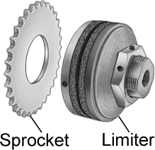
You can see the friction discs of the clutch in this picture. They are normally set and forget type clutches with a belleville spring maintaining the driving pressure to the sprocket. You just turn the machine on and keep tightening the clutch till the machine does what you want under normal loads. I just kind of inverted how they are normally used. If you leave it un-clamped when you don't need power and clamp it when you do then it works for the helve hammer. These devices are relatively inexpensive and dog simple.
Here is a shot of the electronic layout of the helve clutch assembly. The
OSD (overload safety device) is in the center of this cross section of the clutch assembly. The actuator or throwout arm as the automotive guys would call it is on the right side of the drawing. Working out the actuation forces for the clutch was fun. I needed to start with some force that was reasonable and fairly accurate for actuation. This is a machine that is crying for a foot pedal to control the speed and force of the blows. So I started there with the foot actuation force. I have some
human factors engineering books that tell you all kinds of fascinating things about humans and the kinds of knobs, levers and pedals they prefer and are optimal and ergonomic. I wanted a force less than the clutch actuation force for a car and more that an accelerator pedal was okay. The way I determined the force was by stepping on the bathroom scale a bunch of times and getting a number to calculate with and force that my foot and ankle were happy with.
This force drove the design of the foot pedal length and travel as well as the length of the actuation arm for the clutch. As you can see the pedal is connected via a cable to the actuation arm. Its an emergency brake cable for a Ford truck. Once again cheap and mass produced and already engineered by a army of engineers at Ford that want to keep their jobs. Good enough for my project.
In this picture you can see the actuation arm and the clutch in their respective positions. The drive system just sits there and idles once you turn it on. When you step down on the foot pedal the clutch pack compresses and transmits power from the motor to the eccentric on the left of the picture. I chose a v-belt because of simplicity and cost. It also gave me a little more pulley thickness to work with in the clutch assembly for a bearing when the hammer is idling. The clutch works better than expected. It can deliver a single hit or up to 240 hits per minute that will move steel sheet metal easily.
Next installment is the power recovery system of the helve hammer.


No comments:
Post a Comment