There is something about the spherical shape that many machinists find fascinating. If you want proof just open a couple of drawers in almost any machinists tool box and I would bet you find a few spherical objects. Ball bearings are a popular item collected by sphere enthusiasts and are kept next to the random dowel pin selection in your typical toolbox. Over the years I have quoted and done a few interesting spherical jobs that are worth discussing here. At first glance they seem simple enough but work holding and tooling can make what appears simple into a real pain.Below are a few examples from my collection of balls and spheres work.

Ok this first picture is cheating a little. All these were produced in the milling machine using an interesting technique with a rotary table and a boring head. I call it spherical generation because it is the result of two rotary axes intersecting to produce the sphere. Its an old time trick and much more cumbersome that programming the right radius. But it does have the advantage of a self proving systematic error correcting process. In manual lathe or CNC lathe spherical work you depend on tool form accuracy and error free programming and machine motion to produce true spherical geometry.
Diameter of this sphere is around eight inches OD. Two pieces made in stainless steel. Its some kind of pressure testing cell. Why it needed to be spherical inside and out connected by #8 screws is beyond me. Originally the design called for 6-32 screws but we begged for a change to a less break easy size. This job entailed a large amount of material removal and cool workholding problems.
Another gas testing cell. This one was more like a spherical funnel. Two piece split between the mounting screws. This is another one I kick myself because I didn't get enough pictures during the fabrication.
This was a fun G job with some leftover titanium. A job we ran all the time produced some leftover slugs of commercially pure titanium that were much too good to toss in the scrap bin. It applies to this discussion because the inside bottom is spherical.
A full scale drawing of the shot glass used to check tool clearances. The tool needs to be able to pass the center line by half the nose radius of the insert at least. This one was close. I used a big drill to remove most of the material prior to boring. If you include the drill in your electronic drawing you can actually get a very accurate depth dimension for the drill.
For this article I will focus mainly on the two piece full sphere since it has the best photo documentation of the lot. We start the story of the twin balls in the Marvel saw.
The raw material was calculated to be just enough to do the job. We used aluminum to prove the programs and first articles. It took quite a while just to cut off the blank chubs even with full feed pressure. This is an example of something that you generally don't think about when you quote a job like this. In hindsight I should have plowed more than one blade into the quote and doubled the time I allowed for the sawing. The operator didn't have to stand there but there were extra blade changes and because it took a long time to cut there were lots of drive by's.
I started with a short section of the OD that would be used for clamping for the second side. The main work of the first side was hogging out the inside material. There were a couple of problems that showed up when I did the proof parts. The first was I needed to create a ridged tool that had the right geometry that would clear in the bottom and not rub.
I had a boring bar that would clear but it was no way stiff enough to reach into the concave ID in stainless and survive. I priced a new bar from the local tool guy and decided that It made more sense to whip something up in the shop. What helped me make my decision was that I rarely if ever used the donor boring bar anyway. So not spending three or four hundred bucks on a new bar that the first thing I would have to do is cut it down made the call easy.
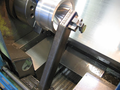
Another lesson was tool wear. The amount of material removal was way beyond what one insert could provide so a way of accurately calibrating a new insert partway through the cut was necessary. My machine was not equipped with a tool sensor so guess what, I had to make one. It was a fun diversion anyway so I didn't mind too much. The machine is an Okuma LB-15 circa 1985. Its a real workhorse and is consistent whether its running plastic or ripping on stainless all day long. I had a good reference surface to attach the tool calibration arm to which was the mounting plate for a steady rest. The trick here is repeatability. I could care less what the calibration numbers were I just needed it to repeat within a few tenths from each removal to replacement. The Okuma has a cool stop function that allows for just this kind of
tool changing operation. You can stop mid cycle and change an insert and
the machine will pick back up right where it left off.

In this picture you can see how OD tools get set using a battery powered touch sensor used in the mill. The handwritten diameter offset number is what I calibrate the tool to when I touch it off.
Since the main job that the sensor was created for had a lot of ID work I added some features to my tool setting contraption to make setting boring bars easier. The indicator is zeroed when the cutting edge to be set is on center. This has the added advantage to manipulate the center height by small increments if you need to.
In this shot of the OD you can see the short section of spherical surface that was turned to provide a clamping surface to machine the rest of the contour. Downslope turning on radii can be a tricky depending on the machine control. The old OSP5000 control on the Okuma is a solid control but with some quirks for downslope radii turning related to tool nose radius compensation.
Boring the pie soft jaws for the OD work with a spider. This was interesting because the clamping surface was re-entrant and spherical to hold the spherical diameter turned on the first side.
Detail view of the re-entrant cut in the softjaws. This gripping surface needs to run true to the spindle axis. The part was checked carefully with an indicator to make sure the blend in of the two cuts matched as well as possible.
After the roughing on the OD. You can see there is just enough of the finish surface near the chuck showing to blend the two cuts together. Here is a link to a
company that makes big balls like this all the time. Their setup for cutting a full plastic sphere is similar to the one I'm showing here.
Article on the some of the problems with spherical turning.
More soon.


How do you work your volume out to get 25ml shot glass?your work looks great
ReplyDeleteHi Unknown,
ReplyDeleteIt just takes a little math. You can get accurate data from the cad system depending on how you model it. If you model it 3D then the volume is pretty easy. Thanks for the comment,
Cheers,
Tom