Ongoing journal of a life spent designing and building special tools, instruments and mechanical devices for the scientific, medical, metalworking and product development industries. Idea's turned into reality by the mechanical pursuits of Tom Lipton (OX)
Sunday, November 4, 2012
Squareness Comparator 2
I did most of the machine work on the the large parts of the comparator gage over the weekend between other activities. There were a couple of interesting mill setups that are worth discussing here. The rod base and the gage base have some radius cutouts and lightening features that required some setups you don't do every day. In general I prefer to do as much perpendicular work as possible to a part before I add angular or any decorative features like chamfers or corner radii. Its always good to leave a part as blocky and orthographic as possible for as log as possible to aid in the accurate registration of subsequent features. If all you have is rounded and angular features it makes it tough to locate anything accurately.
Here is a shot of boring the three bearing or rest points on the bottom of the gage. These are bored for a press pit of three carbide balls that I will grind flats on as the wear resistant feet of the gage.
Tapping holes in the end of the base for the flexure membrane. I have already cut the relief for the radius contact plate and tapped the mounting holes. Neither of these are anything special other than to show the progression leading up to the special stuff.
In this model picture you can see the curved cutouts that serve as gripping notches and weight reducers on the comparator gage. They all have the same three inch radius which makes my setup just a little easier. I decided to use a standard boring head to make these large radius cuts in the parts. The first step was to setup the boring head to the correct radius.
For large holes or radii I like the cross hole bar for a standard boring head. This particular bar uses an insert tool and fits the cross hole in my Criterion boring head. I left the screws slightly loose for the next part. I moved the spindle so that is was exactly 3.000 from the vise jaw.
Earlier I had established my zero on a mill stop and the rear fixed jaw of the vise. I set the boring head so that its slides are centered and the readout is on zero.
This is only out of habit. If I need to move it to make some minor correction its always easier to remember you started at zero instead of on 77-1/3.
Carefully with the spindle in neutral I extent the bar so its was a little further than the 3.000 to the vise jaw. Rotating the boring head backward by hand with a post-it note between the tool and jaw the bar gets pushed back into the head until the tool just scrapes the paper. After securely tightening the bar I double checked that the bar had not moved and confirmed my setting.
Here is a short video of the radius operation. I leave the boring head setting alone. The depth of cut is adjusted by moving the head relative to the work using the DRO on the mill. In this situation I was able to take .075 radially per pass and have it cooperate and leave a nice finish with an interrupted cut.
The part was indicated vertical in the vise prior to making the radius cut.
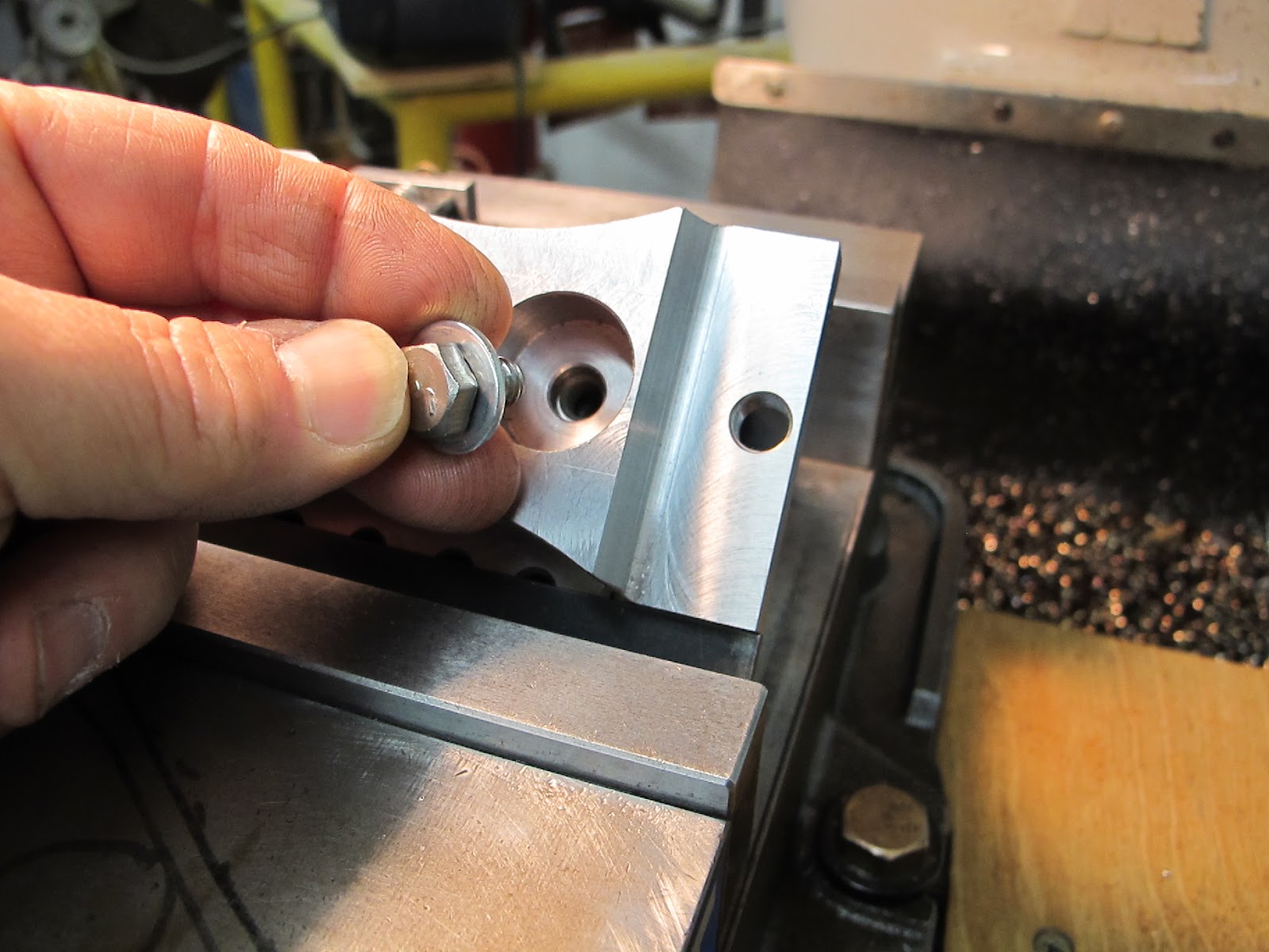
The next interesting setup was another angle cut for a relief on the rod holder. The angle was 45 degrees so there are lots of setup options. I decided to use an small equal leg angle plate I have that had some handy tapped holes in it.
Sometimes you get lucky like I did. My part just happened to have a hole in it that I could get to match up with one of the tapped holes in the angle plate.
That took care of one side. On the opposite end I just used a Kant twist clamp to hold it to the angle plate.
Cutting the relief angle on the rod base. I roughed it with a 1/2 diameter carbide end mill and finished it with a large diameter inserted cutter. The small diameter roughing cutter is gentler on a light duty setup like this.
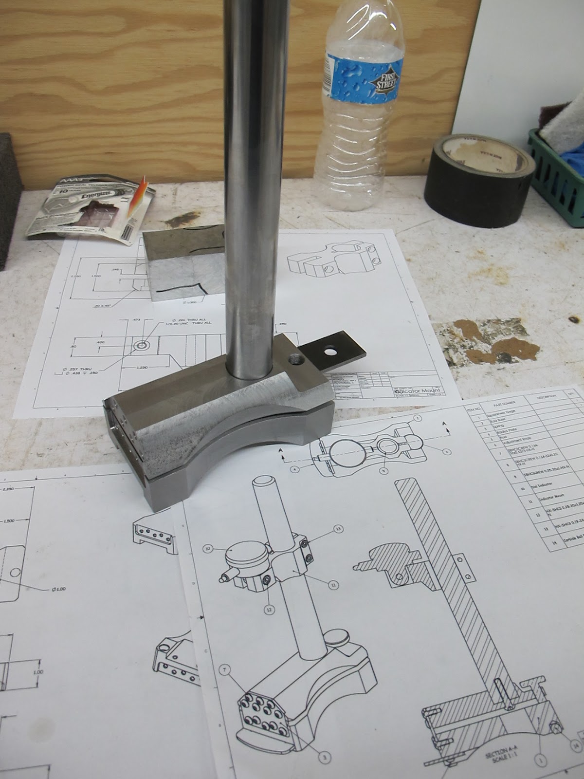
Hey, its starting to look like the drawing. The parallel is between the two parts to add spacing so I could get a feel for how it will look with the flexure membrane installed.
The orientation of the angle plate was not my first choice either. The I really wanted to use the power feed to get the best possible surface finish. This outweighed the potential instability of the angle plate orientation. I used a small diameter end mill to remove most of the material and just did a .003 DOC finish pass with the large diameter cutter. Great comments! Keep them coming.


Looking good.
ReplyDeleteImpressive DOC with the boring head.
Not sure I would of clamped the angle plate in that orientation.
Also didn't know Sony made DRO's. Accurite is the standard over here (UK).
Once again, excellent post and look forward to part three.
Hi Map,
ReplyDeleteThe orientation of the angle plate was not my first choice either. The I really wanted to use the power feed to get the best possible surface finish. This outweighed the potential instability of the angle plate orientation. I used a small diameter end mill to remove most of the material and just did a .003 DOC finish pass with the large diameter cutter. Great comments! Keep them coming.
Tom
kobe basketball shoes
ReplyDeleteair max 2019
westbrook shoes
nike basketball shoes
adidas tubular
kyrie 6 shoes
calvin klein outlet
supreme new york
supreme clothing
air yeezy