Ongoing journal of a life spent designing and building special tools, instruments and mechanical devices for the scientific, medical, metalworking and product development industries. Idea's turned into reality by the mechanical pursuits of Tom Lipton (OX)
Friday, October 19, 2012
Wabble Drive Proof of Principle
About five years ago I built a small etching press for my wife. She has been interested in printmaking for quite a bit longer than that and had a nice press on her wish list. In a moment of weakness I agreed to build her a nice large etching press. This was shortly after looking at one in a studio and making the silly comment, "that looks pretty easy to build". After that she started her campaign to have me to build one to her specifications. As the pressure mounted I suggested that I built her a smaller press so she could get started with printmaking in her own studio. I could build it quickly compared to the larger press she really wanted so she could get something sooner. This had the added advantage that I would learn something from the small press build that would be scale up on the larger model.
The small press turned out good enough that she has been using it for the last five years doing a lot of printing of etchings and smaller monotypes. The need for a larger press is back in full force. Right now a much larger press is in the design department so she can finally scale up the printmaking operation. I decided early on that since I am probably never going to build another press this one should have all the embellishments and look like a piece of art in itself. It will become the center piece of her printmaking studio and a great example a home built press. During the design process I found I needed a gear reduction that had a large ratio in a rather flat package for the press. Typically these big presses have a reduction from the hand wheel to the roll of around fifteen to twenty five to one ratio. This is hard to do cleanly with chains and sprockets or with less than four or more gears.
This is a closeup of the gear reduction I figured out on the small press. I don't remember the exact ratio but its around six to one total reduction in two steps. The gear reduction is necessary because of the high loads during the printing process. As the axial length of the rolls increases the total pressure across the machine can be several thousand pounds. Fine control as the print enters the squeezing zone is one of the features of the high end presses like the American French Tool press. You can see these are massively built machines. Gigantic hand wheels are a signature feature of high end etching presses.
In this photo you can see part of the gear reduction mechanism behind the spoked handwheel. The handwheel input goes through a gear reduction and drives the lower fixed roll of the etching press. The top roll is movable to accommodate different items on the press plate and to vary the printing pressure. Basically a glorified laundry ringer, the inked etching plate gets squeezed between the two rolls and transfers the ink to the paper to produce an image.
Many different designs were scrapped before it settled on something I liked. The following is a description of a unique type of speed reducer sometimes called a wabble drive.
As the design work proceeds on the new large press I wanted to prove out the gear reducer as designed on the computer. This press will take advantage of accurate plasma and waterjet cutting to make many of the profiles used throughout the machine. One set of profiles in particular are in the gear reducer. The hope is that the reducer is insensitive to the tooth shape and will operate with laser or waterjet cut teeth without and finish machining. Also because it is just a little unique and interesting I decided to built a full scale model for testing.
This is the 2D study of the gear reducer I designed. It is officially and mathematically called a cycloidal drive. The slang or old time name is a wabble drive. It is quite simple and easy to construct and if it operates from net shape cut profiles it should be inexpensive. In this AutoCAD layout the input gear is the inner gear with the gear teeth facing outward and the reduced output is seen in the outer gear (teeth facing in). The long slotted arm is to keep the input gear from rotating in a circle. The input gear motion is restricted to an circular eccentric arc which moves the equivalent of one tooth space per revolution of the eccentric.
One of the main reasons we went in this direction is because of how compact this gear reducer is. It has a ratio of eighteen to one in a very flat package. I have never seen one on any piece of equipment which was another motivation for trying it out with a proof of principle. Anybody can put a bunch of chains and sprockets on to make a gearing reduction, but they lack the higher mechanical art that I am striving for in the large press.
Here is a screen shot of the Solidworks model of the handwheel and gear reducer assembly. For scale the large handwheel is four feet in diameter. The plan is to fabricate the large handwheel from waterjet or laser cut sections in several thicknesses of steel to give it the old school cast wheel look. You can see the wabble reducer sitting at the heart of the wheel with the anti rotation arm pointing down.
Here are a couple of nice cast handwheels we spotted at the Alameda antique market. At four hundred bucks each they were out of my price range anyway so I guess I'll be building mine. In the old days they used the double curved arms on cast wheels to control casting shrinkage. As the molten iron cools it contracts causing some wheels to crack. Curved spokes have enough spring in them to prevent breakage.
For the wabble mock up scrounged PVC plate that was close to the thickness that the steel reducer will be the input and output gears. The shop CNC mill just had a major service and servo tune after we lost all the parameters mysteriously and wiped its memory somehow. The mill needed a test and some nice gentle plastic cutting was just the ticket. Later on we will do a ball bar test to verify the servo movements. Watch for an article on that event coming up in the near future.
The input gear anti rotation bar is a piece of polycarbonate rescued from the scrap bin. The extra holes are just fixturing holes where I bolted the material blank to the mill for profiling.
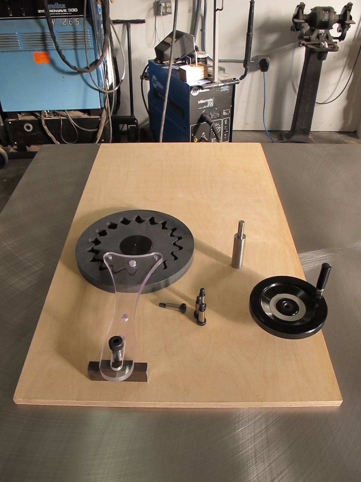
All the ingredients ready for final fitup and assembly. The center eccentric is the black Delrin bit in the center of the input gear. It gets an offset hole through it to mount the handwheel shaft. The eccentric offset gives almost a five eighths sweep of the input gear. There are always several teeth engaged with the output gear so there is no possibility of freewheeling.
Indicating the eccentric boss in so I can bore the eccentric hole for the shaft. I always like three point contact when I hold a round puck like disc in the vise. It is way less prone to tipping than holding it in the normal vise jaws. The back v-block is a aluminum softjaw I cut for doing round parts in the mill. Normally it bolts in and replaces the rear fixed jaw of the vise. Here its just acting like a simple v-block.
This is just a set screw hole to lock the shaft to the eccentric. I wanted to show this picture because before I removed the bored eccentric from the v-block in the previous picture I used a pointed scribe in the chuck to scribe axis lines on the disc. It is a difficult thing to re-pick up two curved surfaces like this eccentric if you need to do something else after you lose the original orthographic reference.
Laying out the output gear retainers for the model. All they do in the model is keep the output gear rotating in the same spot. This is all built on Baltic Birch thirteen ply, plywood. Its the Mic 6 of woods with its super tight laminations and uniform thickness and great flatness.
Couldn't wait for the real handwheel to give it a spin. The vise grips have copper pads brazed to the jaws so they wont mark the shaft in case you were wondering.
This is a short video I shot of the working model. Its fun to watch the inner gear wabble around. I can see how this type of drive got its nickname.
Thanks for looking. Stay tuned for more developments on the design of the large etching press.


yeezy
ReplyDeletekyrie 5 shoes
ralph lauren uk
jordan retro
nike epic react
balenciaga shoes
nike air force 1
yeezy boost 700
michael kors outlet online
off white
Beautifully executed prototype :)
ReplyDeleteyeezy boost 350 v2
ReplyDeletepandora outlet
off white shoes
pandora
curry shoes
pandora charms
golden goose sale
cheap jordans
air jordans
balenciaga shoes