Over the last weekend I worked on the last couple of bits for the comparator gage. The indicator holder was the last major part of the gage needed before I can try it. Nothing too difficult with this part other than has a lot of extra cut features to reduce bulk and make it look a little lighter. Its made from 6061 aluminum which I will probably have anodized later on when I have a few parts to plate. Unfortunately I didn't have a slitting saw large enough to make the split clamp relief so I ended up band sawing it so I can test the gage. I know its a crude way to make the split but I left some material so I can go back in and clean it up if I can borrow a large diameter 1/8 saw.
Probably the most important feature on the indicator mount is the 1.000 bore. This needs to fit the vertical shaft of the gage without a lot of clearance. Just enough so when the clamp is loosened it slip up and down the shaft without having to twist it and shove it. When the clamp screws are tightened it should not move the indicator more than a few thousandths if its touching the work or the reference and lock securely without having to gronk on the clamp screws.
I decided not to use my beloved Rotabroaches for this particular hole. It was necessary to control the fit closely by boring it to size accurately. Notice I'm using a collet on the Silver and Deming drill. For those of you out there that stick these in your really expensive Albrecht chucks, don't do it.
I mentioned in a recent article that I like telescoping gages. Here is a good example of why. I can sneak in along side the boring head under the tool and still get an accurate measurement. When I'm roughing I like to use the most foolproof measuring tool possible until I get close to whatever that tools minimum reliable resolution is. What I mean by that is if I was boring a hole where there was a significant amount of material to remove I would use my tape measure first, then switch to a rule when I dropped below the minimum reliable resolution of the tape measure something like + 1/8. With a ruler I can now approach the finish diameter to within .030 without breaking a sweat. After that I would switch to telescoping gages and calipers.
With calipers and a fussy hole I might go to within .005 of the finish size. Remember this example is for a hole where we might take many passes to get close to the target. When the hole was within .005 or .010 of the finish dimension then I would switch to a micrometer to read the telescoping gage. For my one inch hole I have another tool that works well in bored holes. It does have the disadvantage of needing a bit more room to access the hole to insert the tool.
For the final measurements the Intramike makes it easy. The plug gage on the right is 1.0002 which is what my target number is for the bore on the indicator mount.
I like the plug gage for the final verdict on the hole. It has the ability to evaluate the entire average length of the hole for size simultaneously. Any errors in roundness or taper get averaged with the plug gage inserted the full length of the hole.
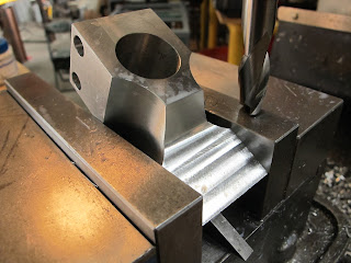
In this picture I'm blending the angle cut into the previously cut flat. There is a .06 radius between the flat and the angle. Angle is 30 degrees.
A couple of shots of the finished indicator mount. I was anxious to try it out and see how the flexure preload was with the gage reading against a square reference. It had a little more that I cared for so I took off the radius plate and removed some material to bring the nominal preload to where I was happy.
There are a few details left to wrap up like the chamfers on the body and rod base and the carbide feet. So one more article for the comparator gage.


No comments:
Post a Comment