Friday, November 1, 2013

5C Spindexer Indexer

A few weeks ago I proposed a follow along project on my YouTube channel oxtools. A viewer suggested an interesting problem involving indexing. His problem was how to accurately index 127 divisions for making a special gear. This might sound trivial at first glance but it quickly becomes difficult with standard tools and indexing devices.

The basic problem is 127 divisions is a prime number. To use standard circular dividing techniques requires compound indexing to achieve 127 divisions. Very few readily available and affordable dividing heads are equipped to do compound indexing without some modification. So what to do? The need for 127 divisions crops its head up when changing the gearing on a manual lathe to switch between inch and metric threading. As it turns out a factor of 127 happens to be 25.4 Starting to sound familiar now?

So now its actually an interesting project which is why were talking about it here. What I proposed in a video is to modify a standard cheap 5C collet indexer in a simple way to handle the 127 problem and make quick work out of typical spacing operations in the average shop.
These 5C Spin indexers are readily available and cheap at around $50 plus shipping. Many folks already have one of these indexers for the very same reasons. The project involves making some additional parts that allow the indexer to quickly index common divisions much like the common but much more expensive super spacer.

These units can already index 360 divisions with the help of a one degree pin vernier. Our modifications will make it quicker and simpler for small numbers of divisions while allowing us to directly index odd numbers like 127 and fractional angular indexes such as 7 or 11. Its limitation will be the ability to create the needed index plates and fit the desired number of hole on it.

Here is an example of an index plate with several patterns of equally spaced holes in it. The outermost circle of small holes has 127 equally spaces holes in it of 1/8 inch (3.17mm) diameter with approximately the same amount between the holes. As you can see in the drawing the disc needed to contain all these holes is pretty large. So large in fact that the stock indexer will not sit on a milling machine table without elevating it with this disc mounted. The maximum diameter that the stock indexer will support without a riser is roughly 5.6 inches.
In this shot you can see the maximum sized disc that can be used on the standard spin indexer when it sits on the machine table. So how do we get the desired 127 holes in a disc that will fit on the indexer without raising it off the table?
This is how we do it. By changing the radius that some of the 127 holes are on we can now put additional circles of holes and reduce the diameter of the disc to something that fits. The trick is that the angular spacing between any adjacent holes is exactly 1/127 of 360 degrees. The radius of the circle that the index hole lies on makes no difference as long as it lies on a radial line from the center of rotation of 1/127 of 360.
Here we see the needed parts to convert the stock 5C spin indexer to a spindexer indexer. In this example we show the 127 hole plate which is a very special case. For most folks a couple of different plates with some common divisions 2, 4, 6, 8, 10, 12 etc will make the most sense. The example of 127 holes is just to illustrate a method for making higher number or difficult number index plates of a small diameter. Obviously some of the common divisions can be indexed using the original plate and pin. The additional index plate speeds repetitive indexes and eliminated any possible errors of reading the angular scale.

The tapered arm is the index detent pin for plates with rows of holes on a single radius. It acts as a flat spring and engages the hole in the index plate with a tapered pin. To do higher order indexes with multiple index hole radii  such as 127 holes it is necessary to use the half index block part number 16. This slotted block allows you to disengage the tapered pivoting arm and re-engage it in another set of index holes on a different radius. The half index block is accurately located on the spindle centerline to avoid any errors caused by angular shifting.

To create the index plates the array of holes is put it using ordinate positioning in X and Y instead of angular indexing. Following the established jig boring practice of locating circular patterns accurately with this method is well understood and documented in books such as "Holes Contours and Surfaces" by the Moore Special Tool company.

The ability of the average shop to position accurately in X and Y rectilinear coordinates is higher than the typical ability to discriminate small angles. A simple milling machine equipped with a digital readout can make short work of making any desired index plate.

What follows are the drawings of the parts needed to modify the stock indexer and make it a spindexer indexer. Builders are encouraged to modify the design to suit their available materials and abilities and desired levels of embellishment and artistic style.


Thanks for looking.

Tom Lipton

Sunday, October 13, 2013

Tiny Drilling

For all the time I've been in shops there has been a story floating around that gets repeated whenever somebody has to drill a tiny hole. The story changes depending on who tells it but basically has the same cast of characters. The story goes something like this.

An American company developed a new drill bit for drilling tiny holes. The story teller never has a specification on how small the drill other than its really small. Smaller than a hair is what I've heard told before. This amazing drill took years of development and the company, once again un-named other than its an American company, is rightfully proud of their achievement in toolmaking.

The second part of the story gets even fuzzier. I have heard it told that the un-named American company had a rival or partner Swiss or German company that somehow hears about the new tiny American drill achievement. They politely ask for a sample of the drill for testing on their application or machinery. The American company rightfully proud, quickly obliges and sends them a drill for evaluation.

Depending on who is telling the story the roles can be reversed. The story seems better if the Swiss or German company is showing off their achievement to the Yanks.

So after some interval of time passes a package arrives back at the drill manufacturers doorstep. They open the package and find the drill bit they sent out. They look it over and see nothing so they send it back again slightly confused. Another time interval passes and the package comes back again. No explanation, no note, just a package with the drill in it. This time they look at it closely. To their utter disbelief they look and see there is a hole drilled through the side of their tiny drill bit.

Recently I bought about thirty pounds of old magazines from a guy at the Alameda antiques fair. I found this article in a old Popular Mechanics from the 1950's. It has almost all the parts of the story except the competition between the Swiss or German toolmakers.


This is from the 1950's Imagine what we can do today. I work with a fellow that has tools as small  as .0004 inches in diameter. Yes, ten microns. You cant even touch the tool with anything without breaking it. It takes a 60,000 rpm spindle to make it do anything. All I know is I would like to see the machinery that tool is made on.

Enjoy.

Tom Lipton

Tuesday, September 17, 2013

Monarch Lathe Survey

I had the opportunity to survey an interesting lathe recently. I appeared on our local Craigslist with a couple of sub-optimal camera phone pictures. Since it was local I sent the guy an email note inquiring about it to see if I could get a look at it. The machine is a 1964 Monarch Model 71 engine lathe. The lathe has a twenty inch swing (500mm) and  is seventy eight inches (2000mm) between centers.This particular machine has a hydraulic tracer attachment along the back side of the bed.
The first thing I noticed was the tailstock. What caught my attention was how massive it was. On closer inspection it has some very cool features.
Starting on the left the quill has very nice graduations engraved into a groove milled into the surface. The diameter of the tailstock quill was like a huge slab of baloney and over four inches around. Surprisingly the internal taper was only a #3 Morse which looked oddly small for such a massively built tailstock. The second cool feature was its own independent oiling system. I even gave her a pump for old times sake. Looking lower below the oiler we see a really nice feature for large lathes. The curved arm headed downward is a hand crank pinion that engages the rack under the ways and allows you to crank the heavy tailstock into position.
In this photo we see a couple of neat things. The lever on top is to change gear ratios for the tailstock. It has three positions, High, Low and Neutral. The lever shifts perfectly even though nobody has moved it in at least fifteen years according to the owner. I must have shifted it a dozen times playing with it. The angled handwheel is much more ergonomic than the standard type at the end of the tailstock.
It doesn't show very well but the cap on the rear of the quill has a graduated dial that reads to .001 (25 Microns). It does not move in and out with the quill it only rotates with no through hole to the quill ID. The lock levers, yes two can just be seen below the handwheel.
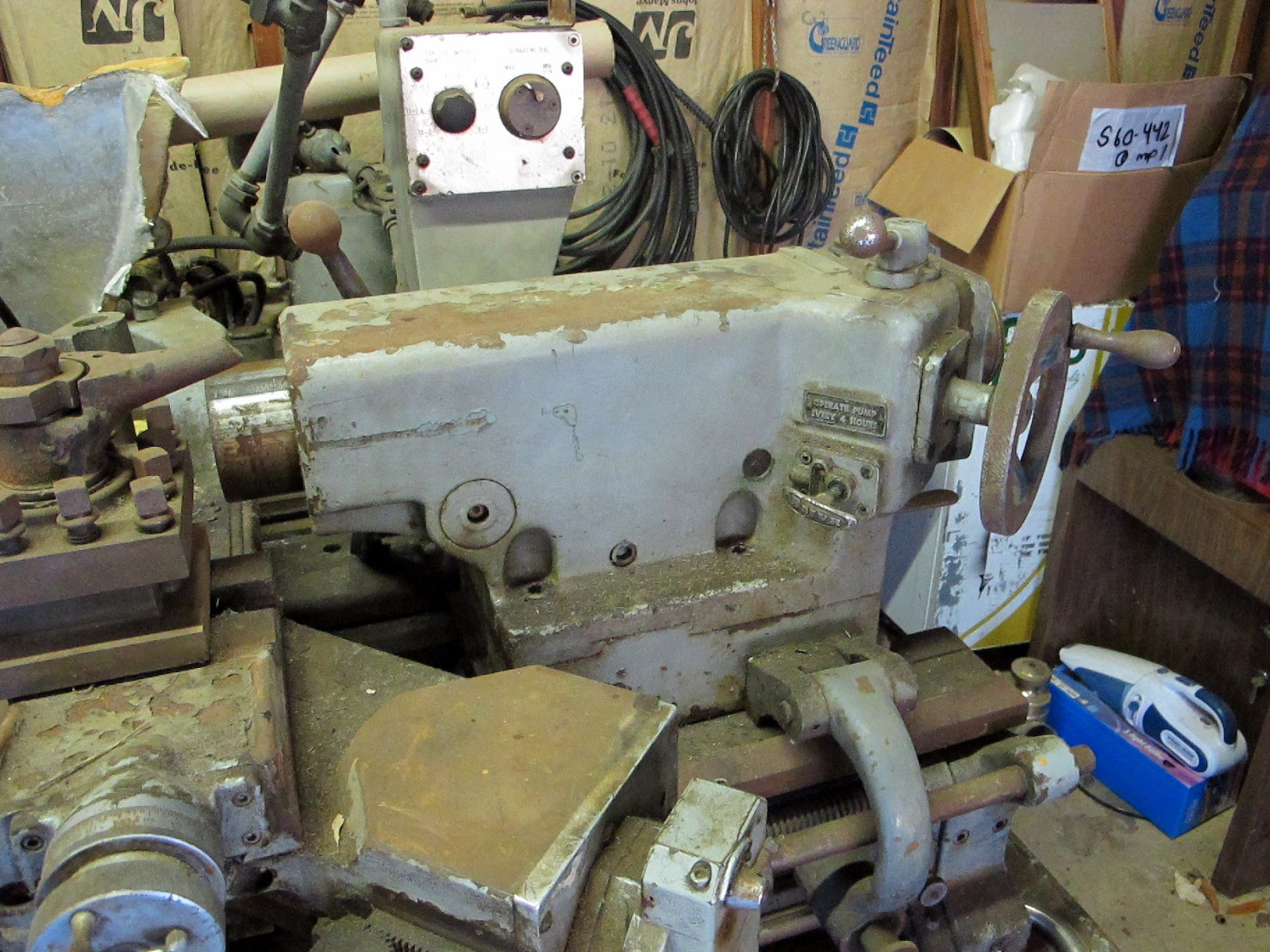
Moving along the machine we see some of the apron and cross slide. She shows some signs of rough handling on the carriage. In this shot you can see the pipsqueak Morse taper hole in the tailstock quill.
Looking down from the top we see part of the tracer attachment and control feedback. This side of the machine must have been bumped with a forklift as the spinning handles on all the handwheels were broken. Thankfully the shafts were not bent. I was able to turn everything even with fifteen years of dirt and dust on it.
I always liked Monarchs dual feed lever setup. No funky shifting required and you can engage both at the same time if you dare. Nice large diameter wheel with fine straight serrations on the rims. In this shot you can also see the center bed support. It has dual chip pans and a center foot support that wraps around. The chip pans are heavy duty and looked to be massive cast bits.
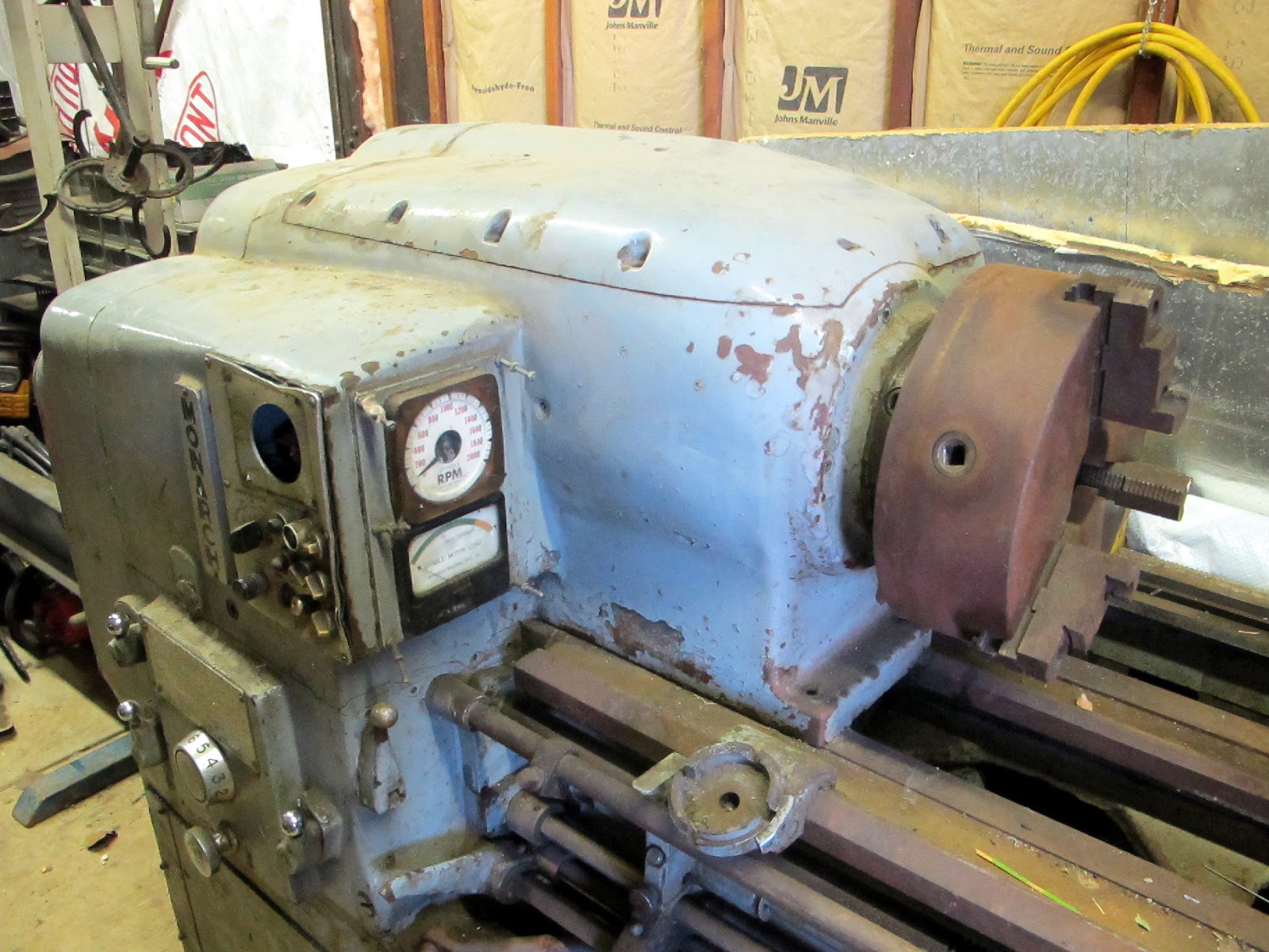
Up near the headstock now. The ways look rusty but in reasonable shape. Unfortunate on the rust but not the end of the world. At least there were no gouges near the typically heavily used chuck area. I believe Monarchs had hardened ways on many of their machines. Cam-lock spindle nose. The though hole was pretty small which is typical of many American lathes.
Here is some of the controls at the headstock. You can see it had electric range shifting and could go from 20 to 2000 rpm. Speed was controlled with the small black knob at the lower left. There was a hole above that housed some kind of electrical gauge not sure what it displayed as there were speed and motor load indicators to the right.
The ball end lever directly below the motor load meter releases the quick change gearbox and it operated probably as good as it did when this machine left the factory in 1964. In fact all the headstock levers moved and detented perfectly. For me this is a mark of quality, smooth operation of all controls with positive detents and engagement. I think the forklift did its damage up here also. The control panel was pushed in a bit. With the exception of the gauge it looked easily repairable.

Another shot of the headstock control area. Here you can see the Monarch badge. Their fonts changed over the years. Looking at this font makes me think fifties or sixties.

Now for the scary part, the electrical enclosure. This machine had some advanced capabilities and features. The tracer is basically a servo system controlled by a template and follower. This requires some control logic in an age of relays and contactors.
In addition to the tracer this machine could deal with changes in surface speed. I would guess it translated the template diameter and controlled the spindle speed to keep a relatively constant cutting speed on the work piece. It is also equipped with some hydraulic system that uses electrically controlled valves to change speed ranges. And it has infinite variable speed control within the major ranges. For all that you need a big box of electrical equipment.

It was a pleasant surprise to see the electrical panel in great shape and pretty un-molested. Monarch in their infinite wisdom even put a copy of the electrical schematic on the inside of the cabinet door. Real class and professional engineering.

I sure had fun going over this machine. Its for sale in the San Francisco Bay area. The price is $.19/lb Yes that's right, nineteen cents a pound. This once proud example of American ingenuity can be had for basically scrap metal price.

The bones of the machine are there and look to be in good shape. It is most certainly not a project for the faint of heart. Just the machine retrieval will be a major expedition. But hey, without expeditions and people willing to go on them where would we be? Somebody with some guts and mechanical aptitude would find themselves with a lathe made by one of the finest American makers with several lifetimes more work in her.

Thanks for looking.

Tom Lipton


Monday, August 19, 2013

Drill Press Vise Wrap Up

I'm calling it done at this point. After cleaning and repairing the bonus Kurt vise I acquired with the Clausing drill press its ready for use. I built a special base and anti rotation arm to make quick work out of clamping the vise to the drill press table.
The vise base is a .50 thick phenolic plate. I had the material left over from another job and it made sense for this application. Its strong and durable and wont mark the table. It has the perfect amount of friction that allows the vise to move around but is not so slippery that the vise will move under heavy drilling. The vise mounts to the plate via a couple of Helicoiled tapped holes. The notch is for the steel anti-rotation arm. I just scribed around the base of the vise casting and band sawed the profile and notch to match. You can see my chicken sketching on the side of the flat bar arm.
I wanted the anti rotation arm to be one inch wide. All I had in stock was two inch wide material. Nothing is easy right? I band sawed the two inch lengthwise and then milled the edges. Something to note when you do this type of splitting of a rolled bar. The cut immediately opens up and the two pieces come out curved from the stress relieving cut. I have had this happen before so I allowed extra cleanup stock so I would finish one of the bars to one inch wide. The clamps are holding a strong back back bar to keep the narrow bar from vibrating while machining.
So in this shot we see the vise mounted to the base plate and the anti-rotation arm attached. I found a cheap swivel socket wrench at HF that seems to work as a decent replacement for the missing Kurt article.
My McMaster box arrived today so I was able to complete the anti-windmill arm clamp. I think we all have a horror story on the drill press that we could relate. Its nice to not have any roadblocks to doing the right thing with clamping on the drill press.
The clamp allows the arm to slide in and out and pivot when loosened. When the clamp lever is cinched down the vise is locked in place. It can be quickly and easily removed if you need the entire surface of the drill press table for a large part. The Kurt vise is pretty heavy so it makes for a solid drilling experience.

So my famous drill press story goes like this. I was making some special plastic starwheels for a bottle filling machine. These look like big sprockets with teeth the same shape as the bottle being filled. Their purpose is to time and guide the bottles into the filling machine. These particular wheels were made from PVC plastic plate. It takes two star wheels to make a set they are connected by a spacing hub and attached with flat head screws. I needed to countersink the mounting screws after drilling the holes in the plates. We used to make these in the pre-CNC days by carefully pasting a full scale drawing on the material and then band sawing the curves and arms of the star wheel. It took a few hours to do a nice job on these with the sawing, sanding and filing. The mounting holes were one of the last operations.

We did a lot of 316 stainless in that shop so my countersink was pretty hammered. I went and got a brand new countersink from the machinist tool crib to use on my nice new star wheels. I remember it well because it was 3/4 inch in diameter and sharp as a scalpel. I saved a trip on the way back by picking up a flat head screw from the bolt bins to gage the countersink diameter. The mill was being used so I decided to use the drill press in the welding shop to countersink the holes.

Here where it starts to get interesting. I remember saying to myself, "I'll just hold this down by hand to the table" See this is how it starts, one little dumb thing. The next thing I told myself was, "I don't need to set the depth stop, It takes so long to run the damn thing down so far" I chucked up the countersink and set the drill press speed fairly slow.

These things happen so fast it always surprises me. The millisecond the single lipped countersink touched the edge of the pilot hole it snagged and sucked my star wheel plate right off the table. I somehow managed to hold onto the plate but all that did was make the countersink actually drill through the plate. Instead of a countersink for a 1/4 flat head screw I now had a three quarter inch diameter round hole in its place. My butt tightening event was over in about 500 milliseconds.

Every time I need to countersink soft plastic from that point on I either have the part securely clamped, or the cutting tool is non powered. Fortunately for me PVC cements well so I was able to make a plug and glue it in and re-drill and countersink the hole and save the part. With that cement the countersinking lesson was permanently bonded to my hard drive.

Thanks for looking.

Tom Lipton

Thursday, August 15, 2013

Kurt Vise Root Canal

A few articles ago I wrote about a pleasant machinery surprise I found. The surprise was a nice four inch Kurt vise that came with my Clausing drill press for nothing. The vise was pretty hammered when I started working on it. Originally I thought it was an offshore knockoff and even considered trading it away for something else. Lucky for me I decided to give it a bath and take a closer look.
The vise was in pretty sad shape when I started in on it. The jaw mounting surfaces were whupped from clamping parts with no jaws. The handle is lost to who knows where and the replacement is welded in place no doubt to prevent its loss. A fine patina of sulfur based cutting oil residue rounds out the gruesome picture.
The moving nut has seen the business end of too many drill bits to count. One bonus here is the table of the drill press is relatively unmolested. Probably because the vise took the bullet for the team protecting the table. Look closely at the divits on the right side of the nut. They look a little wonky to me so I started picking at them with a awl. I was able to pop out a couple of loose fillings made of epoxy.
A few minutes in the dentist chair and now we have a clearer picture of the necessary dental work. I don't understand how somebody keeps drilling in a situation like this. The one hole at the top of the image goes halfway past the vise screw. I know now why the bozons patched the holes with JB weld or bondo. They had to keep the chips out of the screw or nothing would work.
Many of the edges of the vise were chowdered up like this. A trick a dutch toolmaker showed me a million years ago is instead of filing the raised burr off is to displace the material back into position. You will need a smooth flat faced hammer. Its important that the edges between the face and the side of the hammer are rounded so you don't get a bite mark if you hit off angle.
The trick is to hammer and direct the blows so the face hits flat. If your careful and work slowly generally you can push the material back into position pretty well. If you file it off its gone forever.
A little careful tapping and the corners are mostly back where they belong. Its going to take more than a little tapping with a hammer to get this vise looking good again.
The first step in fixing the Swiss cheesed vise nut was to make a copper mandrel to fit inside the threaded hole through the center. The purpose of the mandrel is so any weld metal doesn't get into the threads. The nut would be difficult to re-thread in the lathe because of its awkward shape and odd size and left hand to boot.
The copper mandrel fits in the threaded bore with a easy slip fit. I expect this to get a little stuck after the welding.
A short preheat and it will be ready for welding. Looking for something like three or four hundred degrees F or so. Hot enough to smoke the old cutting oil.
I'm TIG welding the holes with 1/8 diameter Ni-99 rod. Tungsten is 3/32 diameter Lanthanated DC straight polarity. A reader has been asking me what kind of current I'm running on some of these jobs so I set the camera up and took a picture.
I did it twice and the current was the same at 100 amps. The machine was set in the high range which is the upper scale on the right hand meter.
It took two filler rods to fill the cavities up to this point. If I was really a dentist this would be called a trans-cavity bridge filling.
While it was still hot It got wrapped in a fiberglass blanket and allowed to cool overnight. Next up will be the mandrel removal.

The next day I went to work on removing the copper mandrel. Driving into work I thought of a good way to drive it out by just inserting the lead screw and pushing it out. I was so happy I thought of an easy way to push it out I was thinking about it during the day.
It was a great idea for about half way. The mandrel stopped moving so I had go to plan B and get medieval on it. I ended up cutting if off short and drilling as big a hole as I dared in the now dead soft copper. If you haven't experienced dead soft copper and drill bits consider yourself warned. After drilling a pretty good sized hole through it still wouldn't come out so I used a jab hacksaw to split the copper tube that was left of the mandrel and collapse it into the hole. I didn't take any pictures of this process as I was annoyed and just wanted to get it done.
I did some sanding on the weld buildup to make it look more presentable. It least the holes are patched and no chips will get down into the screw and nut assembly.
The finished product. Not factory new but definitely better than usable. I made a set of steel jaws with a built it parallel step and vertical vee groove. Not a bad ending for a vise that was close to its expiration date. I called Kurt to ask if they had parts for this vise. I was told this vise is a very early model. The clues were the five inch width and the lack of a needle thrust bearing in the screw. This dates it to the dawn of Kurt history. A real relic.

Thanks for looking.

Tom Lipton