I was looking through some old pictures and I ran across a group that I took when I built my large English wheel. For those of you that are not familiar with this tool it is a manually operated old school sheet metal shaping machine.Typically English wheels are used to make compound curves like you would see on car and airplane bodies These versatile machines can also make a variety of straight bends with simple tooling that is easily fabricated in the shop. Sorry for the low quality pictures. This project was done around 2001 and I had a low quality digital camera.

Like most useful skills and occupations English wheels take some time and dedication to master. I would not call the English wheel a money making machine. This is one of the reasons you don't see many of these in fab shops. The high level of operator skill and slow forming speed limit the productivity in a job shop. English wheels are found in high end auto restoration shops and one man operations that can afford to put the time in required to master and use these specialized machines.
All that said I still wanted to have one to learn the art of compound metal shaping. Most industrious folks make their own wheels so why should I be any different. I started out with testing other peoples wheels and discovering what features I liked and didn't like.
A little background in how one of these machines works is probably in order. There is quite a bit of bad information on the web related to English wheels so I recommend you do your own independent research to help filter the garbage out. Good sources of information are the metal shaping forums that have been around for a while like
Metalmeet and
Metalshapers.
There are as many methods for shaping sheetmetal as there are people teaching classes on how to do it. There is no doubt that they all get excellent results with their different methods and tools. I would caution you to observe and judge for yourself when somebody tells you there is only one right way to do something. You will quickly discover there are "Wheel People" and "Hammer People" Come to your own conclusions to where you find yourself.
An English wheel is just a glorified giant c-clamp. In fact here is a picture of a small English wheel made from a c-clamp.It works fine. I have driven this one myself at a get together of metalshapers I hosted in the shop I ran.
The frame just provides a convenient place to mount the two wheels in relation to one another. The wheels are the important part of the machine. Typically a standard English wheel is set up with a large diameter flat faced upper wheel and several easily interchangeable smaller diameter lower wheels.
Rectangular tubing is easy to fabricate into a English wheel frame. Here is a shot of the frame for my wheel during construction.
Upper Wheels.
There is a wide range of wheel diameters and widths found in popular English wheel construction. The most important factors for good results are large diameter, 3x or 4x the lower wheel diameter, minimal runout better than .005 TIR, flat highly polished face, and hopefully hardened to maintain the fine finish. Excellent results can be achieved with less than these minimums but at the expense of greater operator skill and knowledge. Re-machined large diameter casters and large ball or roller bearings are excellent candidates for English wheel upper wheels.

An picture of my friend Wray Schelin's English wheel with a large ball bearing upper wheel. He is working a piece of bronze for an art project demonstration. The advantage of the bearing as an upper wheel are inherent precision, surface finish, and high surface hardness. The face of the upper wheel is typically in contact with the exterior surface of the material being shaped. If the contact surface is not smooth it will imprint its surface finish on the work like a copy machine. Likewise if the upper wheel has a mirror finish it will also impart that high quality finish onto the surface of the shaped material.

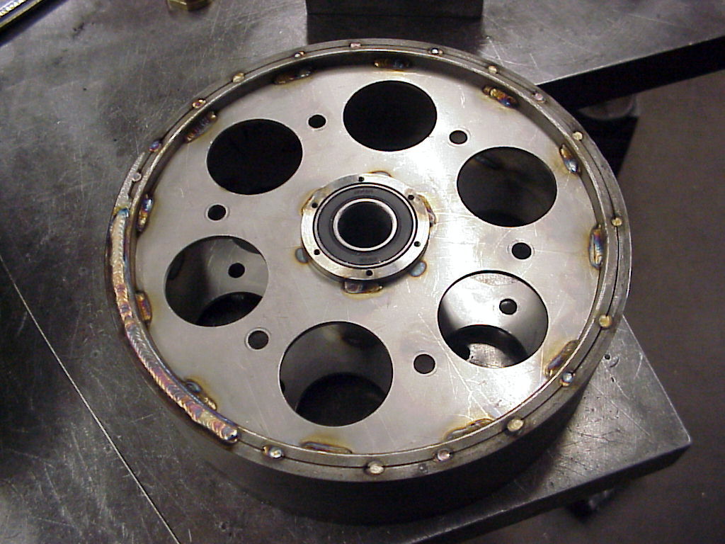
When I built my wheel I decided to fabricate the upper wheel from scratch. My primary goal was low inertial weight. It was fabricated from flat material rolled up and welded together. Having a low inertial weight pays back when you are operating the machine. Your arms and back have to stop the wheel at the end of each stroke and re-start it in the opposite direction. When I test drove a wheel with a solid upper wheel the inertia was quite noticeable as well as the fatigue.
The wheel material is 17-4 PH stainless steel. The outer rim is two layers .25 thick welded together. Side plates are 10 ga 304.
The finish machined upper wheel. It was turned between centers off the bearing bores to get the best concentricity.
Lower Wheels/Anvils.
Making the lower anvil wheels is more involved. They are relieved to allow the sheet to curve downward. Contrary to some popular belief this curve does not do any part of the forming operation. It is merely clearance for the curved sheet. The secret is the center flat of the lower anvil. The flats vary in width and are what does the actual forming of the sheet.
Think of a tire running down a muddy road. The tire displaces or stretches the mud and pushes it out the sides. This is exactly what is happening with an English wheel. The metal is displaced at right angles to the direction of rolling by the squeeze between the upper and lower flats. A rolling linear hammer is another way to think about how the English wheeling process works.
You can see in this picture that the material is just touching in the center where the flat is on the lower anvil. The side relief curvature on the lower anvil just provides a place for the material to flow. The curve also provides some support to the sheet for keeping it level during the wheeling strokes. The contact patch is theoretically a line but in reality similar to a tire contact patch which is more elliptical.
Here is a selection of lower anvils. The differences are the flat widths and the amount of relief. Typically an anvil with a relief slightly tighter than the desired curvature is chosen. To avoid putting tracking marks in the sheet the process might proceed incrementally using anvils with greater amounts of relief as the sheet becomes more curved.
There are several ways to make lower anvils for an English wheel. If you have a CNC lathe the process is simple. I have generally used the manual step turning technique to make all of the lower anvil wheels for my E-wheel. Step turning can either be done following a template or by calculating the coordinates of each cut on the diameter. If you have a simple electronic drafting program its easy work to figure out the coordinates of the cuts along a curve.
Here is a typical lower anvil. The amount of relief or drop is 3/8 inch. The actual radius is irrelevant. What is important are the transitions between the center flat and the relief. These need to flow into each other with near perfect tangency or else the mismatch will show up in the formed sheet as unwanted tracking lines.
In this picture the relief has been divided up into a series of cuts that are .050 diameter reduction. The step increment can be anything you want. The smaller the increment the easier the steps are to blend into a smooth curve.
In this picture the end points of the steps are dimensioned to where they intersect the relief curve on the anvil.
One half of a large lower anvil for my friend Wray. He provided a template for the curve that he wanted. I calculated the cuts to produce the curve and match the template.
You can see in this picture that the corners of the cuts all touch the template.
Partway through the blending process. If the steps are small then there is very little material to be removed to fair the curve.
In this picture the curves are fully faired but not polished. Wray wanted to do the important flat to relief transition himself.
The last ingredient to an English wheel is a way to control the relationship between the two wheels. This is where I see lots of different ideas. The design requirements are simple. The wheels need to be brought together in a controlled and repeatable way. There should be some provision to adjust either wheel so the flats can be brought into accurate parallelism. You cannot rely on precision frame fabrication to provide the necessary accuracy. The relationship between the two flats varies with pressure and frame stiffness so some type of adjustment is needed to maintain parallel flats.
I used a simple flexure to provide the needed adjustment for parallel flats. This is a picture of an experimental Delrin lower anvil for final smoothing of thin soft sheets.
I chose a threaded upper and lower wheel adjuster and large hand wheel. Having a large range of adjustment is useful for alternate types of tooling for the English wheel. Fine thread screws give the needed resolution of adjustment. Acme screws are not necessary for the light loads encountered on the English wheel. They are much too coarse for and require extra operator effort to use.
In this picture you can see both the upper and lower adjusters. The lower has a quick release mechanism to assist in extracting the formed sheet. After using the wheel for a while I found this to be unnecessary. An anti rotation feature is needed to maintain parallelism of the two diameters.
Anti rotation feature for the top adjuster. Two flats on the moving part of the shaft. Washer material is Aluminum Bronze riding on a stainless steel shaft.
Alternate tooling
The English wheel is not restricted to compound forming. With a little creative thinking and some tooling this machine can do some things that machines costing tens of thousands of dollars would find difficult to produce.
Rubber wheel forming. Unlimited length radius bends can be produced with this technique. The soft upper wheel acts as the die to produce a bend with a radius equal to the lower wheel form. Accurate tracking is important with this technique.
Edge tipping an wiring can be done as well. This is a setup my friend Wray uses for bending narrow flanges either along straight or curved edges.
More tooling for long straight radius bends. Compliments of Wray Schelin.
For some of the ideas seen in the alternate tooling a useful adjustment is the ability to bias the lower anvil position in relation to the upper. In this picture we see a dovetail adjustment that allows the lower anvil to shift in either direction.
So in closing if your thinking about building an English wheel I suggest you test drive one before hand. There are enough of these machines out there that its simple statistics that there will be one near you. All of the guys that I have met in the metal shaping craft have been open and eager to help folks starting out. So don't wait any longer. Get out there and try one. I'm sure you will have fun and meet some interesting people.
Links for additional reading.
Imperial Wheeling Machines
Wray Schelin
Thanks for looking.


This is excellent work... What do you have invested in materials on this?
ReplyDeleteI have been working on a 1979 mustang was thinking about making some IMSA Fender Flares.
http://1979-93mustangrestoration.blogspot.com
Hi Restoration,
DeleteI scrounged most of the materials and components. I probably had a few hundred dollars in miscellaneous bearings and materials that I had to buy.
Thanks for the comment.
Best,
Tom
Thank you for an extremely informative and interesting article.
ReplyDeleteI've been involved with woodworking most of my adult life but recently have thought about metal working.
I've just recently begun a cafe racer project so minor metal fabrication is in order.
Thanks for broadening my horizon a little.
Hi John,
ReplyDeleteI don't allow folks to piggyback on my content with advertising and no real comment.
Thanks for you understanding.
Tom
This comment has been removed by a blog administrator.
ReplyDeleteHi Tom
ReplyDeleteVery interesting. I also am a wood machiner, and more recently a plastic forger and machiner. But I have always wanted to build machines. Tell me, how do you fair the lower anvils?
Cheers
Ed
Hi Ed,
DeleteNormally if doing it by hand I use a 4 inch mini grinder with sanding discs to fair and polish the relief. The relief is a non critical surface and does not need the low runout that the forming flat of the anvil needs. Thanks for the comment.
Cheers,
Tom
thanks for the info..i been thinking of fabricating one but buy the anvils and top wheel from ebay...i dont know anyone with a english wheel to try it out .. i just trying to collect info before i build it so im going right direction ...thks bones from essex in uk
ReplyDeleteis Dong dong23 having a lend?
ReplyDeleteExcelente, muy bueno!!!
ReplyDeletecalvin klein underwear
ReplyDeletecoach outlet online
kyrie shoes
coach factory outlet
polo ralph lauren
yeezy 500
off white nike
golden goose sneakers
air max 97
goyard handbags
Hi!exellent work there!im building my own version and would like to get ideas or instructions for the lower anvil quick change.how should i make it?thanks,H
ReplyDeleteBeen looking for anvils for a home made English Wheel. This is exactly what I needed. Thanks
ReplyDeleteThis is all excellent information - - THANK YOU!! FYI, your friend, Wray Schelin, that link to him, it's dead. Sounds like he is doing interesting work too, is there an updated link to him/his work? Thanks!!!
ReplyDeleteHi John,
DeleteWray has a large presence on the web. Did you try searching with his rather unique name? He has YouTube videos now.
Cheers,
Tom
Great advice here....
ReplyDeleteI appreciate the sharing of information...I have watched several you tube videos now That Wray has done, very informative, excellent resource for learning, adding to my 30 plus years of doing bodywork, and paint...A whole another world, in building your own fender, cowl, or even entire car. So thankful for Wrays expertise and willingness to share..
I will be signing up for a class in the near future!
Happy Trails.
kyrie 5 shoes
ReplyDeletemichael jordan shoes
golden goose
hermes handbags
curry 5 shoes
retro jordans
curry 8
supreme clothing
jordan shoes
supreme new york
Do you have the frame plan of the english wheel?
ReplyDeleteNice articles and your information valuable and good articles thank for the sharing information metal wheel guides
ReplyDelete