Recently we built a linear particle accelerator to shoot lithium ions into a metal foil target to study warm dense matter as part of fusion energy research. In the heart of the accelerator are a series of high field pulsed solenoid magnets spaced apart along the length of the accelerator. These magnets are used to shape and kick the beam as it moves along the machine. For the function of the machine these magnets (27) all had to be very accurately aligned to one another and to the machine as a whole.
To compound the difficulty of aligning these solenoids they are inside an atmospheric pressure chamber buried deep inside a high vacuum chamber. Alignment, or even adjustment of the magnets after the machine was assembled would be impossible. The only choice was to align the magnets accurately prior to sealing them up inside the machine.
To start the process we built a special machine to measure the exact center of the magnetic field of each of the magnets before we sealed them up inside the machine forever. During winding and epoxy potting of the magnets small tolerances stack up to make each magnet somewhat unique. Each of the magnets was installed in its own special housing that also had small differences adding to a system error or offset. The magnet measuring machine uses a stretched wire that passes through the solenoid opening. The magnet is pulsed during testing which caused the wire to vibrated with a waveform we can analyze. The wire can be moved in space until the exact magnetic center is found nulling the vibrations. The basic problem is the magnetic center is not necessarily at the same position as the mechanical center of the physical magnet.

Each magnet had to be aligned to a angular tolerance of ten milliradians or less in tilt and less than 30 microns in X and Y. To provide alignment adjustment there is a system of flexures that are used to align the magnets for tilt and XY displacement. All this is pretty straightforward until you find out there are large magnetic forces axially along the solenoid axis when each magnet pulses. This force was calculated to be around 900 lbs.

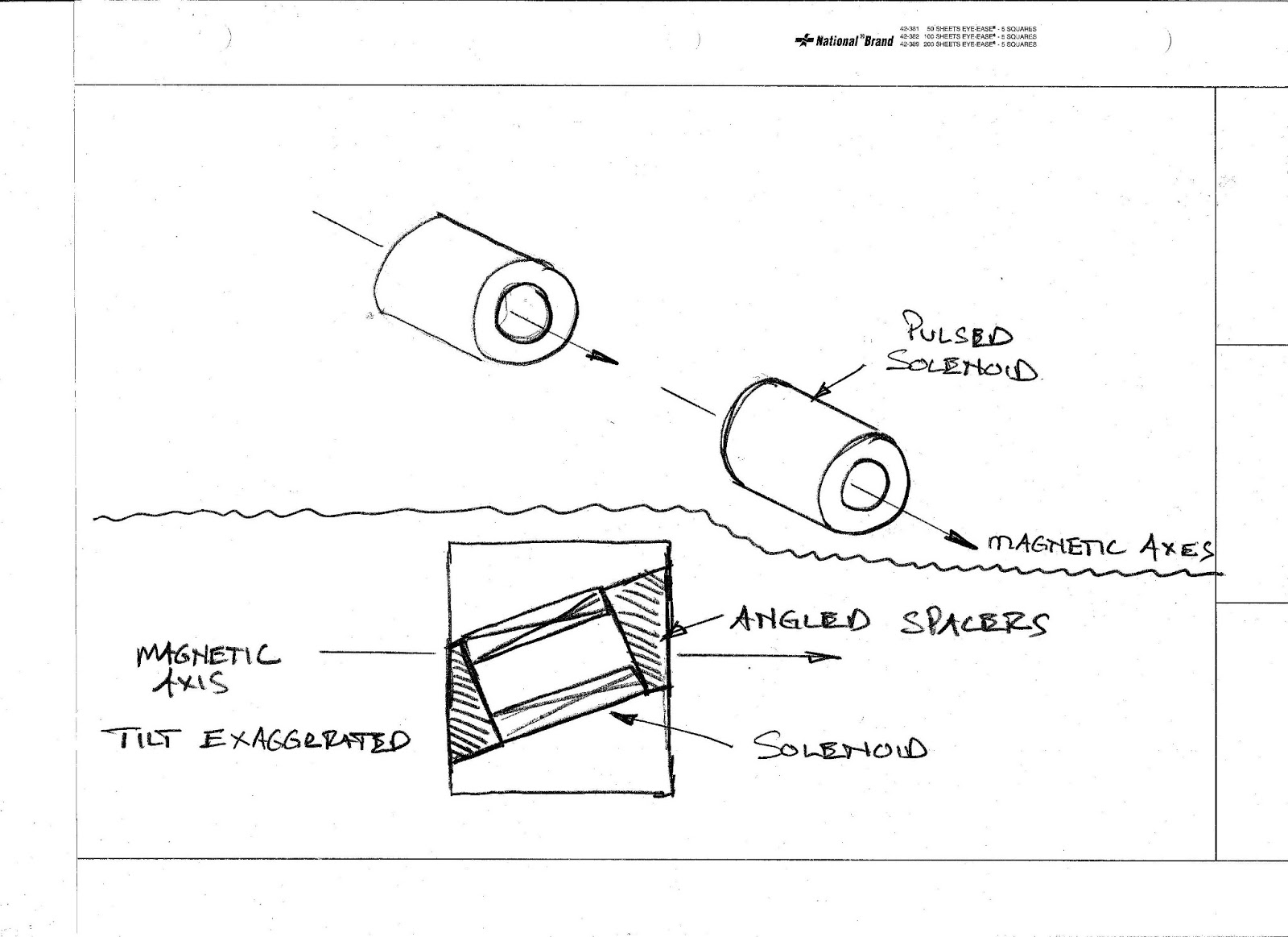
To do this job we used a special tilt table that I built many years ago. Angle setups are among the most difficult and demanding jobs that most machinists encounter. If your angular setup is not perfect the results will be sub-optimal. I personally use the sine bar for many of my angular setups because they are easy to use and very accurate. In the case of these special spacers the angles were very small, on the order of one tenth of a degree. The sine bar can easily handle small angles like this but the work holding part of the job made it a better job for the tilt table. One problem with sine bars is the limited options for mounting parts directly to them for machining. Somebody out there invent a Kurt vise that has sine rolls built into the bottom and a good way to lock it to the table for real machine work.
The scientist taking the measurements gave us the angular data as a dimension over a distance with a radial clocking reference. So we might get numbers like .015 inches over the diameter of the spacer which was 8.5 inches. Saying it another way is .015/8.5 which describes the angle enough for machining. Using the tilt table its a simple matter to set this angle using a dial indicator and a parallel.


Because the top surface of the tilt table is festooned with tapped holes I can use it with the mini pallet strap clamps for a variety of workholding options. I find it most useful for longer low angle work such as doctor blades or single bevel cutting edges. The table is most stable when set to a low angle and its long clamping surface provides lots of holding options for the work.
Thanks for looking.
Awesome!!!
ReplyDeleteYou work to tolerances I never knew existed. What blows me away, is how you tackle the job, and more importantly, how you explain it to us.
My life is good, I have read, and understood the long awaited post!
Cheers
Ian.
Phew, glad you liked it.
ReplyDeleteBack to the shop to make another batch of machine crack.......
Regards,
Tom
Lol!!!
ReplyDeleteWhat a great idea. A small table that clamps in the vise is always a handy thing to avoid dialing in the vise. Making it tilt really ups the ante. Thanks much for sharing, I really enjoy your webpage. Very best regards, Tom Bruzan, Mount Prospect Illinois http://radiotelegrapher.wordpress.com/
ReplyDeleteHi Tom,
ReplyDeleteThanks for the comment. I loved the story about the queen's wooden crown.
Best,
Tom Lipton
Tom...this is my next project, have to build a copy of this....question...does the round have a flat milled on it where it meets the plate? Got the round ready, now just have to hit the rem store for the plate
ReplyDeleteHi Chuck,
ReplyDeleteYes the rod has a flat on it. Its a wide enough flat that there is some room around the bolt clearance holes. I used 3/8 diameter socket head cap screws.
Regards,
Tom Lipton
ReplyDeleteYes the rod has a flat on it. Its a wide enough flat that there is some room around the bolt clearance holes. I used 3/8 diameter socket head cap screws. buy facebook fanpage reviews
longchamp bags
ReplyDeletenike sneakers for women
supreme
adidas nmd
air max 95
curry 6
100% real jordans for cheap
yeezy boost 350
yeezy shoes
jordan retro
browse around here buy replica bags online browse this site 7a replica bags wholesale you could look here www.dolabuy.ru
ReplyDeleteExcellent write-up—this is a fascinating blend of precision machining and high-level physics. The way you solved the micro-angle alignment challenge is truly impressive. Thanks for sharing such detailed insight—professionals who value precision, like those at Landmark Tools, can really appreciate this level of craftsmanship and problem-solving.
ReplyDelete